Using Stack Table Layouts in the Stacker work area makes it easier to visualize and control how processed parts will be unloaded from a processed sheet on the laser shuttle table. In the Stacking Module a user may create various Table Layouts that reflect shop floor conditions. A table layout is built around a part-removing robotic arm that unloads just-cut parts from a processed sheet and stacks them on pallets located on other adjacent tables or carts.
Parts are never placed directly on tables; they are placed on pallets that are on the stack tables. For this reason it is necessary to create Pallet Layouts first, before attempting to create a table layout. See Pallets Menu for more info.
Note: For the Stacking Module to function normally, the user must first 1) Auto Sequence and then 2) Unload the sheet. Depending on user settings, both steps can be completed while the sheet is in the Cut Sequence work area. However, if a sheet is unloaded in the AP100US work area, it will be carried out according to default settings (see Cut Sequence tab). If desired, a sheet can be unloaded in the Modules work area. Unloading in Modules gives the user more precise control over the process. Sequencing and Unloading create the necessary SY2 and NC files that the Stacker (and Automation Simulator) require to function.
Create a Table Layout
![]()
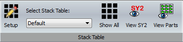
Setup
By default the Stacking Module opens with only one "Default"
table. Other tables may be added and configured as needed. To create Table
Layouts that work in conjunction with pallets, click the Setup
icon to open the Stack Table List
dialog.
Note: Create table layouts that take into account the size of the sheets that are used in the AP100US program, which reflect the size of the sheet metal, shop floor tables (or carts) and pallets that are used in your shop.
1) The Stack Table List dialog lists the stack tables that exist. The first table layout is Default, which may be configured.
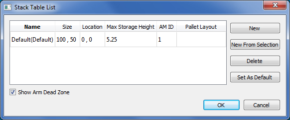
Double-click to enter text directly into the fields in each row
Size controls the overall dimensions of the table.
Location controls where the table will be located in relation to other tables. In the above image the <0, 0> location is the default base point.
Max Storage Height is the maximum height that a stack of parts may reach. For multiple sheets of the same layout, the part Stacker will meet the max height for part stacks and make new stacks as needed to nest all the parts in the job. If the Storage Height is decreased, more stacks will be created; if the Height is increased, stacks will be taken away, but the same amount of parts will be placed on the table.
AM ID is the ID number for each table; the user must enter numbers for each table (1, 2, 3 and so on).
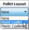
Pallet Layout allows the user to select which Pallet Layout will be used in a particular Stack Table Layout. After Pallet Layouts have been created, double-clicking in the Pallet Layout field displays the Pallet Layout pull-down. From there the user may choose a Pallet Layout.
Control Buttons
Click New to create an entirely new table layout.
Click New from Selection to create a duplicate of an existing selected table layout.
Click Delete to delete a selected table layout (one table layout must remain).
Highlight a row and then click Set As Default to have a particular layout open in the work area when the Stacker is first opened.
OK / Cancel Click OK to confirm changes or click Cancel to discard changes and close the Stack Table List dialog.
Show Arm Dead Zone
This checkbox allows the user to switch ON/OFF the PSR Arm Dead Zone function,
which shows the "reach" limitations of the Part Remover arm.
See Part Stacker Module>Stack
Parts for more info.
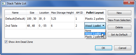
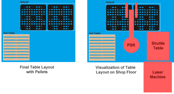
2) The "2nd Table" has been added to the Stack Table List dialog. Notice that the "Plastic 2 pallets" layout has already been selected for the Default table layout, which, at twice the size of the "2nd Table" layout, can handle two pallets. The "2nd Table" layout is only 48"x48" so the Pallet Layout with only one pallet is selected.
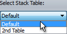
The image on the left shows the resulting overall table layout in the Stacker work area with this configuration. The Default Table ID location is the 30, 0, while the 2nd Table layout is at 0, -55. (To view all table layouts simultaneously click the Show All icon discussed below.) The image on the right is a visualization of the same table layout (not shown to scale) that may be used on the shop floor. When arranging and configuring such a layout, the user must keep in mind the PSR arm "reach" limitations. See Part Stacker Module>Display Arms for more info on this.
While working in the Stacking module, the user may return to the AP100US work area at any time to edit the sheet or cut sequence. After a table layout has been created and saved in the Part Stacker module, the same stacking table arrangement is also visible in the AP100US work area.
Note: The Default table is the first table that parts will be unloaded to when Auto or Auto all are selected.
Select Stack Table
Select this option to view and edit a particular Stack Table layout in the work area. All table layouts available are listed here.

If the user
has the necessary equipment and Part Conveyor has been selected in TK
Unloader Settings, then the Conveyor
option will appear.
See TK Unloader Settings for more
info on this option.
![]()
Show All
To view all stack tables in the work area at the same time, click Show All. This view allows the user to arrange the overall layout of all tables with pallets. Table layouts cannot be edited in this view.
![]()
View SY2
To view the editable SY2 file (which contains stacking code) click View SY2. Clicking this icon updates the SY2 file to reflect recent changes.
The original SY2 file for a sheet is auto-generated in the AP100US program when the sheet is unloaded. As the user edits the unloaded parts and arranges pallets and table layouts in the Stacker, the SY2 file is automatically updated. The system does not auto-save, so when the user exits the Stacker (to return to AP100US for instance) all work must be saved. See Part Stacker Module>File Menu for more info on saving.
![]()
View Parts
Click to view parts on all parts on the table layout in the work area. This option shows the parts on the table and also in the Part List. Click a part in the list to see its location on the table. If this option is selected when the Show All option is enabled, then the default table layout will display.