
The Automation Simulator module gives the user an accurate simulation of the part removal operation, before the actual operation is carried out on the machine floor. This can save programmers and operators valuable time by identifying issues before they turn into costly problems.
Note: The machine in the background may differ somewhat from your machine.
View a Simulation
In the AP100US Interface
Begin in the Modules>Unloading sub menu by clicking on the View Unload Sequence button shown here -

The current unloading sequence will only be viewable only when the part removal operation in the AP100US interface has been finalized, and the NC and SY2 files have been generated (see Cut Sequence>NC for more info). The current sheet that is active in the AP100US Modules work area will be loaded into the Program List when the module launches.
If the user would like to view the unloading sequence in the AP100US work area without launching the Simulator and before the NC or SY2 files have been generated, make sure that the PSR>View Unloader in 3D check box is OFF. Click the View Unload Seq. button to view the unloading sequence.
Note: The Simulator supports part removal arms up to and longer that 70 inches.
Note: This button may be clicked at any time open the Auto-Simulator to view previous part removal operations that have a saved SY2 file.
Note: An SY2 file (*.sy2) is a part pickup definition NC file that contains part pickup data.
Note: The above instructions only apply when the TK part remover is in use. If other machines are in use, clicking this button will still allow the user to view the unloading sequence, but only in the AP100US work area.
Note: If the sheet has been saved with a pallet in the Part Stacker, that pallet will also appear in the Simulator (as shown in the image above).
See View Part Unloading for more info.
In the Automation Simulator Interface
When the Simulator opens the current sheet file should already be in the Program list as shown here -
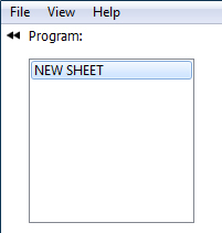
The user must select that file and then click the Play button in the simulator to view the part removal simulation.

Standard
video options control the simulation
File Menu
Click the Load folder to open previously generated SY2 files, in order to view a simulation again. SY2 files by default are saved to the installation folder (such as, C:\AP100US\NCFiles). Select an SY2 file, click Open and the program asks you to select the matching Sheet file that was generated along with the NC file. Click Open to run that file in the Simulator.
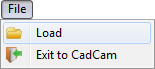
Click Exit to CadCam to return to the AP100US program work area. With this option the Simulator does not close, but will remain running in the background and no changes will be lost. The user may return to the Simulator at any time.
However, when the red X in the upper-right corner is clicked the Simulator will close completely and changes will not be saved.
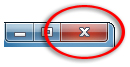
Click the Red X to close
without saving changes
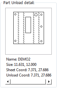
Part Unload Detail
The
part being removed at the moment displays with part info in the Part Unload detail field.
As the Simulator removes the next part, it will display in this field.
Check the Display Stacked Parts... box to display stacked parts from preceding programs.
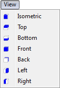
View Menu
The View menu allows the user to choose view angles for the simulation.
Zoom Controls
Return the simulation view to normal size and position by clicking the first (home) button.
Reduce the view by clicking the second (X) button.
Zoom the view with the third icon by dragging out a box around the area to be zoomed and left-clicking.
![]()
The box icon also gives a drop-down menu with isometric view options.
Control the View by mouse
In the simulation view, left-click and drag to rotate the view.
Click the center-button and drag to pan the view.
Right-click and drag the cursor diagonally to zoom the view in and out.