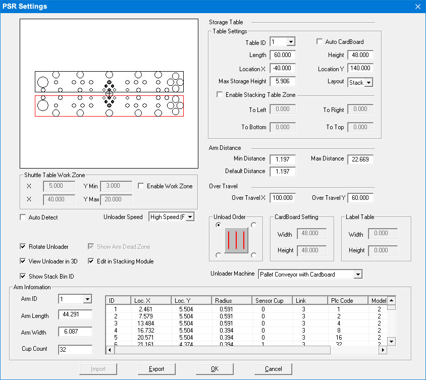
When you select Info from the Unloading submenu, the PSR Settings window will appear. The options in the window allow you to specify the settings for the arms and storage table that compose the unloading device.
Notes:
1. When you select an arm, it will turn red in the preview area.
2. When you select a cup, it will turn red in the preview area.
3. Click the cells in the Arm Information table and make modifications to individual suction cups.
4. The options that appear in this window depend upon the driver/machine loaded.
Option
Description
Preview Area
The arm layout and suction cup layout will appear in the Preview area.
Storage Table
The settings in this section define the storage table parameters after the parts are removed from the machine.
Table Settings
Settings here are for the stacking tables in the Part Stacker module. Besides a configurable Default table, more tables can be created by the user.
Table ID
Select the table to be configured from the pull-down menu. Tables are created and numbered by the user in the Stack Table List dialog.
Check the option ON to allow cardboard to be inserted between part layers in the AP100US work area. Cardboard insertion can be switched ON or OFF as needed for individual Table IDs and then saved by clicking OK. To set the size of the cardboard sheet, see CardBoard Setting below.
When parts are stacked from the processed sheet to the stacking table, a sheet of cardboard is inserted between part layers. This options supports multiple part layers.
Note: This option does NOT affect cardboard insertion in the Part Stacker Module.
Length / Height
The length and height of the storage table.
Location X / Y
Configure the X and Y coordinates of the table selected.
Max Storage Height
The allowable maximum storage height.
Layout
Layout methods include Sheet and Stack for auto unloading are supported. Sheet will place the parts as they appeared on the original sheet. Stack will stack the same parts (with the same rotation) one on top of the other within Max Storage Height limits. Hit <S> on your keyboard to toggle Sheet to Stack to Sheet.
Check ON to enable a Stacking Table Zone for the Part Remover Arm.
To prevent a collision with adjacent equipment
or barriers, this option controls the range of a PSR arm's movement,
while the arm is placing parts on a stacking table. 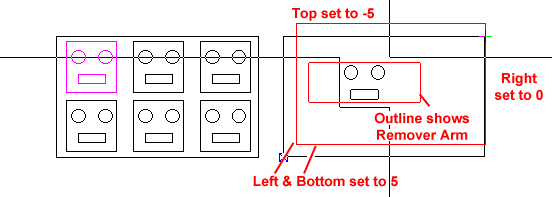
Unload a part to the stacking table, and when the arm (with part attached) is dragged from the shuttle table to the stacking table, it cannot be moved outside the red stacking table zone.
Enter values for: To Left, To Right, To Bottom and To Top. A negative number extends the zone beyond the boundary of the stacking table. A setting of 0 allows the PSR arm to pass freely outside the zone on that perimeter.
Arm Distance
The settings in this section define the minimum and maximum distances between the arms.
Notes: Arm Distance does not include arm width. The Simulator supports part removal arms up to and longer that 70 inches.
Min Distance
The allowable minimum distance between the two arms.
Max Distance
The allowable maximum distance between the two arms.
Default Distance
The default distance between the two arms.
Over Travel
Specify the vertical maximum over travel for the arms to ensure the arms are within the specified Y traveling range.
Over Travel X
Set the value for overtravel in X.
Over Travel Y
Set the value for overtravel in Y.
Note: If the Y value of the parts exceed the “Over Travel Y” value, AP100US will always set “arm2 (or B arm)” as the based arm.
Enter values in the X and Y fields to control which parts will be unloaded from a shuttle table to the stacking table. This allows an operator to control the movement of a PSR arm in areas with limited space, and can help eliminate collisions between the PSR arm and adjacent equipment or barriers.
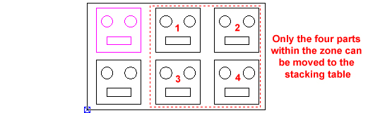
Even though more parts may be on the shuttle table after cutting, only parts within the Zone can be moved to the stacking table.
Auto Detect
If you place a check mark in the Auto Detect check box, the system will detect the cup status (On/Off) automatically when you edit the arm.
Unloader Speed
Select the unloading speed from the drop-down list.
Rotate Unloader
Check this box to allow the arms of the TK Unloader to rotate.
Note: This is a driver-dependent option, and will not function with all drivers.
Show Arm Dead Zone
Check this box ON to show a dashed red line on stacking tables indicating the extent or "reach" of the part remover arm. When this option is enabled, parts will show a small circle that indicates the pickup center.
See Part Stacker Module>Stack Parts for more info.
View Unloader in 3D
Check this box ON to enable viewing the part remover simulation.
Edit in Stacking Module
Check this box ON to enable editing in the Stacking Module. This is enabled by default. To edit stacking in the AP100US work area, uncheck this box.
Note: When stacking in the CAM program the system will use settings from the Auto Stacking Layout Settings dialog in the Stacking Module.
The separate Stacking Module may not be needed by some users. However, by default the module itself continuously runs in the background, impacting system resources. This toggle allows the user to switch off the module when it's not in use by removing the check in the box.
When the check is cleared the Edit Stacking icon remains active. When clicked the Stacking Module will not launch, but the user will be able to manually drag parts to the stacking table, while remaining in the AP100US interface.
Show Stack Bin ID
Check this option ON to show the Stack Bin ID #.
Unload Order
Allows the user to select the unload order. The image shows the order starting in the upper left corner and moving in the Vertical order.