![]()
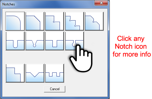
The Notch Library option on the Draw submenu allows the user to apply notch patterns to intersecting lines that comprise the part boundary. Create a basic notch or chamfer, or complex multi-notches, U-notches and V-notches. Select the Notches icon to open the Notches window shown here -
|
Each
icon represents a notch type -
|
To precisely position notches try the Coordinates panel in the Draw menu.
Note: Make sure that Snap Points On in Preferences>Display Options is switched on when using this option.
Important: When placing a notch DO NOT close the Notch window.
|
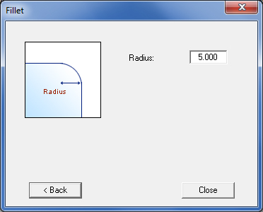
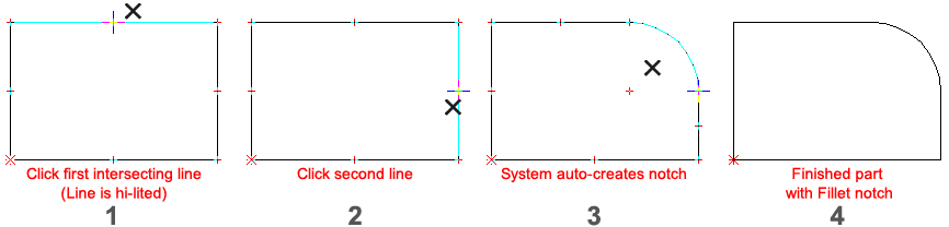
Click the Fillet button in the Notching window to create a fillet or corner radius. You can specify a radius range of 0.001 to 1000000 in the Fillet window. Type a value in the Radius text box and the system will prompt you to select two intersecting lines. Move into the work area and click each line in succession and the system will apply the arc and trim the lines. Important: When placing a notch DO NOT close the Notch window. |
|
|
||
|
Option |
Description |
Radius |
Type a value in the text box to specify the radius. |
|
Back / Close |
Click the < Back button to return to the Notches window to select a different notch type. Click Close to exit. |
|
Important: When placing a notch DO NOT close the Notch window.
|
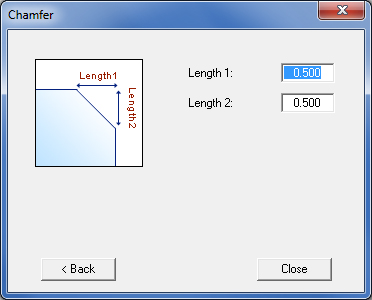
Click the Chamfer button in the Notching window to create a chamfer. Specify the distance from the intersection point by typing values in the L1 and L2 text boxes respectively. Specify a range of 0.001 to 1000000 in the L1 and L2 text boxes and the system prompts you to select two intersecting lines. Move into the work area, click each line in succession and the system will apply the chamfer and trim the lines. See Placing a Notch for a basic example.
|
|
|
||
Option |
Description |
|
|
Length 1 |
This value is where the chamfer begins on the first line. |
|
Length 2 |
This value is where the chamfer begins on the second line. |
|
Back/Close |
Click the < Back button to return to the Notches window to select a different notch type. Click Close to exit. |
|
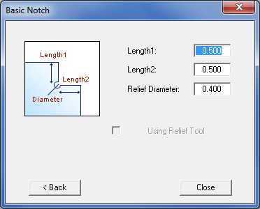
Click the Basic Notch button in the Notching window to create a basic notch with a relief hole. Specify the distance from the intersection point by typing values in the Length 1 and Length 2 text boxes, and the diameter of the relief hole in the Relief Diameter text box. You can specify a range of 0.001 to 1000000 for Length 1, Length 2 and Relief Diameter. As an alternative, you can specify a round tool to create the relief hole by placing a check mark in the Using Relief Tool check box. Move into the work area, click each line in succession and the system will apply the notch and trim the lines. See Placing a Notch for a basic example.
|
|
|
|
|
|
Option |
Description |
|
Length 1 |
Length 1 determines where the notch begins on the first line, measured from the end point of the intersection. |
|
Length 2 |
Length 2 determines where the notch begins on the second line, measured from the end point of the intersection. |
|
Relief Diameter |
Type a value to specify the diameter of the relief hole. |
|
Using Relief Tool |
If you place a check mark in the Using Relief Tool check box, the system will apply the round tool designated as a relief tool (Use for Reliefs). The system will display a warning message if there is no designated relief tool in the turret, and will subsequently open the Turret Information window. You will have to add a suitable tool and designate it as a relief tool, or designate an existing tool in the turret as the relief tool. |
|
Back / Close |
Click the < Back button to return to the Notches window to select a different notch type. Click Close to exit. |
|
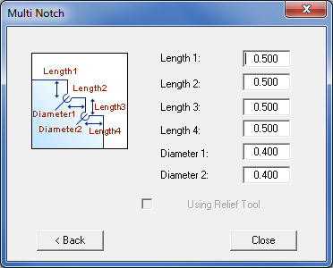
Click the Multiple Notch button in the Notching window to create a set of chamfered notches with relief holes. While you can specify a range of 0.001 to 1000000 for Length 1, Length 2, Length 3, Length 4, Diameter 1 and Diameter 2, there are some constraints that you must observe. As an alternative, you can specify a round tool to create the relief holes by placing a check mark in the Using Relief Tool check box. Move into the work area, click each line in succession and the system will apply the notches and trim the lines. See Placing a Notch for a basic example.
|
|
|
|
|
|
Option |
Description |
|
Length 1 |
Length 1 determines where the first notch begins the line, measured from the end point of the intersection. |
|
Length 2 |
Length 2 determines the depth of the first notch. |
|
Length 3 |
Length 3 determines the depth of the second notch. |
|
Length 4 |
Length 4 determines where the second notch ends, measured from the end point of the intersection. |
|
Diameter 1 |
Type a value to specify the diameter of the first relief hole. The value must be less than the minimum combined distances of Length 1 and Length 2: |
|
|
Diameter 1 < Min (Length 1, Length 2) |
|
Diameter 2 |
Type a value to specify the diameter of the second relief hole. The value must be less than the minimum combined distances of Length 3 and Length 4: |
|
|
Diameter 2 < Min (Length 3, Length 4) |
|
Using Relief Tool |
If you place a check mark in the Using Relief Tool check box, the system will apply the round tool designated as a relief tool (Use for Reliefs). The system will display a warning message if there is no designated relief tool in the turret, and will subsequently open the Turret Information window. You will have to add a suitable tool and designate it as a relief tool, or designate an existing tool in the turret as the relief tool. |
|
Back / Close |
Click the < Back button to return to the Notches window to select a different notch type. Click the Close button to exit the window. |
|
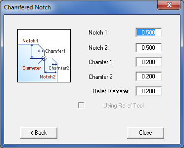
Click the Chamfered Notch button in the Notching window to create relief notch with a set of chamfers. While you can specify a range of 0.001 to 1000000 for Notch 1, Notch 2, Chamfer 1, Chamfer 2 and Relief Diameter, there are constraints you must observe. As an alternative, you can specify a round tool to create the relief hole by placing a check mark in the Using Relief Tool check box. Move into the work area, click each line in succession and the system will apply the Chamfered Notch and trim the lines. See Placing a Notch for a basic example.
|
|
|
|
|
|
Option |
Description |
|
Notch 1 |
The height of the notch, measured from the horizontal line. |
|
Notch 2 |
The width of the notch, measured from the vertical line. |
|
Chamfer 1 |
The length of the first chamfer. The constraint is: Chamfer 1 < Notch 1. |
|
Chamfer 2 |
The length of the second chamfer. The constraint is: Chamfer 2 < Notch 2. |
|
Relief Diameter |
Type a value to specify the diameter of the relief hole. The constraint is: Relief Diameter < Min(Notch 2-Chamfer 2, Notch 1*(Notch 2 - Chamfer 2)/(Notch 2-Chamfer 2+Chamfer 1). |
|
Using Relief Tool |
If you place a check mark in the Using Relief Tool check box, the system will apply the round tool designated as a relief tool (Use for Reliefs). The system will display a warning message if there is no designated relief tool in the turret, and will subsequently open the Turret Information window. You will have to add a suitable tool and designate it as a relief tool, or designate an existing tool in the turret as the relief tool. |
|
Back / Close |
Click the < Back button to return to the Notches window to select a different notch type. Click the Close button to exit the window. |
|
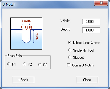
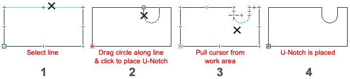
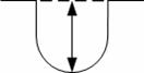
Click the U-Notch button in the Notching window to apply a U-Notch to a line. While you can specify a range of 0.001 to 1000000 for the Width and Depth, the Depth value must be greater than or equal to the Width value. The Base Point options, P1, P2 and P3, determine the relative starting position of the U-Notch relative to the end point of the selected line. The selected base point will appear as a small circle after you choose the line. Move into the work area, click a line and a U-Notch indicator will appear. Select the position for the U-Notch and the system will apply the U-notch and trim the lines. The option will remain active until you cancel the operation.
|
|
|
|
|
|
Option |
Description |
|
Width |
Type the actual size of the notch. |
|
Depth |
Type the depth of the notch. For U-Notches, the Depth is measured perpendicular from the selected line to the radius of the arc. The constraint is: Depth >= Width. |
|
|
|
|
Base Point |
Choose the relative starting position of the U-notch from the end point of the selected line. |
|
P1 |
The start point will begin relative to the left of the end point of the selected line. |
|
P2 |
The start point will be centered relative to the end point of the selected line. |
|
P3 |
The start point will begin relative to the right of the end point of the selected line. |
|
Nibble Lines & Arcs Single Hit Tool Slugout Connect Notch |
When Nibble Lines & Arcs is selected, the program will assign a nibble tool to the pattern. When Single Hit Tool is selected, Connect Notch will be auto-checked ON and the program will assign a single Obround tool. When Slugout is selected, Connect Notch will be auto-checked ON and the program will assign a Round tool and a Rectangle/Square tool to slugout. When Connect Notch is checked ON, the notch will have a closed boundary. |
|
Back / Close |
Click the < Back button to return to the Notches window to select a different notch type. Click the Close button to exit the window. |
|
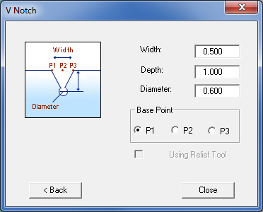
Click the V-Notch button in the Notching window to apply a V-Notch with a relief hole to a line. While you can specify a range of 0.001 to 1000000 for the Width and Depth, there is a constraint for the Diameter. As an alternative, you can specify a round tool to create the relief hole by placing a check mark in the Using Relief Tool check box. The Base Point options, P1, P2 and P3, determine the relative starting position of the V-Notch relative to the end point of the selected line. The selected base point will appear as a small circle after you choose the line. Move into the work area, click a line and the V-Notch indicator will appear. Select the position for the V-Notch and the system will apply the V-Notch and trim the lines. The option will remain active until you cancel the operation. When assigning, a V-Notch will snap to snap points. After snapping to snap point, left-click to move the notch. Left-click again to finalize the position and allow the notch to be resized by dragging it. |
|
|
|
|
|
Option |
Description |
|
Width |
Type the actual size of the notch. |
|
Depth |
Type the depth of the notch. For a V-notch, the Depth is measured perpendicular from the selected line to the center point of the relief hole. |
|
Diameter |
Type a value to specify the diameter of the relief hole. The constraint is: |
|
|
Diameter < SQRT(Square(Width)+Square(Depth)) |
|
Base Point |
Choose the relative starting position of the V-notch from the end point of the selected line. |
|
P1 |
The start point will begin relative to the left of the end point of the selected line. |
|
P2 |
The start point will be centered relative to the end point of the selected line. |
|
P3 |
The start point will begin relative to the right of the end point of the selected line. |
|
Using Relief Tool |
If you place a check mark in the Using Relief Tool check box, the system will apply the round tool designated as a relief tool (Use for Reliefs). The system will display a warning message if there is no designated relief tool in the turret, and will subsequently open the Turret Information window. You will have to add a suitable tool and designate it as a relief tool, or designate an existing tool in the turret as the relief tool.
|
|
Back / Close |
Click the < Back button to return to the Notches window to select a different notch type. Click the Close button to exit the window. |
|
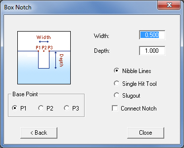
Click the Box Notch button in the Notching window to apply a box or channel notch to a line. While you can specify a range of 0.001 to 1000000 for the Width and Depth, the Depth value must be greater than or equal to the Width value. The Base Point options, P1, P2 and P3, determine the relative starting position of the box notch relative to the end point of the selected line. The selected base point will appear as a small circle after you choose the line. Move into the work area, click a line and the Box Notch indicator will appear. Select the position for the box notch and the system will apply the box notch and trim the lines. The option will remain active until you cancel the operation. |
|
|
|
|
|
Option |
Description |
|
Width |
Type the actual size of the notch. |
|
Depth |
Type the depth of the notch. For channel notches, the Depth is measured perpendicular from the selected line to the radius of the arc. The constraint is: Depth >= Width. |
|
|
|
|
Base Point |
Choose the relative starting position of the U-notch from the end point of the selected line. |
|
P1 |
The start point will begin relative to the left of the end point of the selected line. |
|
P2
|
The start point will be centered relative to the end point of the selected line. |
|
P3 |
The start point will begin relative to the right of the end point of the selected line.
|
|
Nibble Lines & Arcs Single Hit Tool Slugout Connect Notch |
When Nibble Lines & Arcs is selected, the program will assign a nibble tool to the pattern. When Single Hit Tool is selected, Connect Notch will be auto-checked ON and the program will assign a single Rectangle tool. When Slugout is selected, Connect Notch will be auto-checked ON and the program will assign a Rectangle/Square tool to slugout. When Connect Notch is checked ON, the notch will have a closed boundary. |
|
Back / Close |
Click the < Back button to return to the Notches window to select a different notch type. Click the Close button to exit the window.
|
|
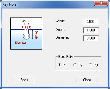
Click the Key Hole button in the Notching window to apply a keyhole notch to a line. While you can specify a range of 0.001 to 1000000 for the Width and Depth, the Depth value must be greater than the Width value. The Base Point options, P1, P2 and P3, determine the relative starting position of the key hole relative to the end point of the selected line. The selected base point will appear as a small circle after you choose the line. Move into the work area, click a line and the Key Hole indicator will appear. Select the position for the key hole and the system will apply the key hole and trim the lines. The option will remain active until you cancel the operation. |
|
|
|
|
|
Option |
Description |
|
Width |
Type the actual size of the notch. |
|
Depth |
Type the depth of the notch. For key hole notches, the Depth is measured perpendicular from the selected line to the radius of the hole. The constraint is: Depth > Width. |
|
|
|
|
Diameter |
Type a value to specify the diameter of the hole. The constraint is: |
|
|
Diameter < SQRT(Square(Width)+Square(Depth)) |
|
Base Point |
Choose the relative starting position of the key hole from the end point of the selected line. |
|
P1 |
The start point will begin relative to the left of the end point of the selected line. |
|
P2 |
The start point will be centered relative to the end point of the selected line.
|
|
P3
|
The start point will begin relative to the right of the end point of the selected line.
|
|
Back / Close |
Click the < Back button to return to the Notches window to select a different notch type. Click the Close button to exit the window. |
|
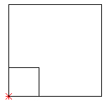
The Regular Corner Notch button in the Notching window allows you to create a notched cutout in the corner of the part without a relief hole. You can add as many corner notches to a corner as required to form the desired cutout. The system prompts you for the corner, and the length and width (X and Y) values. Notes: When the system encounters a corner notch, it punches the entire corner. If a corner contains more than one notch, you can create additional notches using the snap points of the notches you have already drawn as the new corner points. Since the system punches out the entire corner for a corner notch pattern, use the Line pattern when you only want to punch around the notch. When you select Fix Up, the software trims all lines to the notch. If all the notches are different sizes and you use Fix Up, the center points of the lines are no longer the same as the center of the part.
|
|
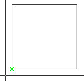 |
After
selecting the Regular Corner
Notch
icon the Notch Library window
will close. Move the crosshair near the corner where the notch
will be placed. Right-click to have the crosshair jump to the
corner and then left-click to attach.
IMPORTANT - The corner must be precisely selected for this feature to function. (If you are using the Coordinate panel to place the notch, then key in <0X> then <0Y> and then left-click to attach.) |
|
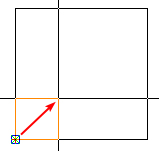 |
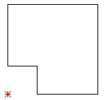
Proceed to drag out the notch into the part (indicated by the red arrow) with the crosshair and then left-click to finalize. | |
 |
At this point the notch may be edited by clicking the New Depth button in the Corner Notch property window to change the overall depth of the notch. After clicking New Depth, when the cursor is moved again into the work area, it will snap immediately to the origin point of the most recently added corner notch. Resize the notch again by dragging it in or out (making it smaller or larger) or by typing in coordinates as mentioned above. At this point it is still possible to adjust the size of the corner notch using the Edit tool. |
|
 |
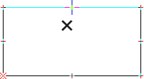
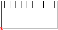
When the size of the notch is satisfactory, click the Fix Up button in the Corner Notch property window to clean away any lines left over after the previous step. |
|
The Regular V Notch button in the Notching window allows you to create a notched cutout on any side of the part. The system will prompt you to select a center point for the V notch. You must specify the depth and angle after you have selected the center point. |
|
|
|
|
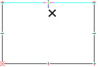 |
After
selecting the Regular V Notch icon
the Notch Library window
will close. Move the cursor near the line where the V notch will
be placed and click. For the notch to appear inside the part,
place the cursor inside.
|
|
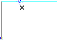 |
Proceed to drag the notch with circle along the line and click to place. | |
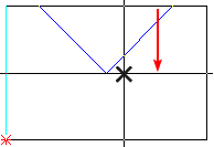 |
Drag the V notch inwardly (in the direction of the red arrow) to enlarge the notch size. Click to place.
|
|
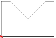 |
When the size of the notch is satisfactory, click the Fix Up button in the Pattern Properties window to clean away any lines left over after the previous step. | |
 |
The
notch may be edited in the Pattern
Properties
window. If the Angle or the center point of the notch is adjusted,
gaps will appear in the part perimeter as shown in this image.
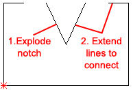
To close any gaps the notch must first be exploded into two separate lines. Select the Edit>Explode option and click the notch. Then select one line of the notch using the Edit>Trim/Extend tool. Repeat for the next line. |

 |
The Regular Multiple Notch button in the Notching window allows you to create a notched cutout on any side of the part. The system will prompt you to apply an array of grouped Channel, U-Notch or V-Notch patterns to an existing line pattern. You must select a line and then the notch type before you can specify the values. When you have completed the notch, move into the Multiple Notches property window and click Fix Up. |
 |
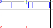
After selecting the Regular Multiple Notches icon the Notch Library window will close. Move the cursor near the line where the Multi-notch will be placed and click. For the notch to appear inside the part, place the cursor inside. |
||
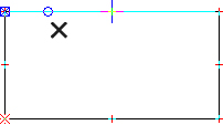 |
When
the line has been selected the circle will appear. At this point
the Pattern Properties window
will appear and the user must select the notch type from the Current
Type
pull-down. Go with the default Channel
Notch
(used in this example), or select U-Notch or V-Notch.
When a Notch Type is chosen, proceed to drag the notch with circle along the line and click to place. See info on the Channel Notch, U-Notch and V-Notch Properties fields. |
 |
|
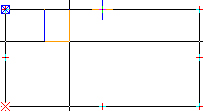 |
Drag out the first notch and click to place.
|
||
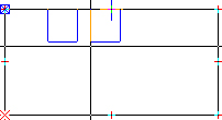 |
Drag the cursor and click to place the next notch. | ||
 |
Drag the cursor to the end and click to place the final notch. The program automatically fills in the space with extra notches. | ||
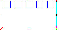 |
Edit the notches in the Pattern Properties window. | ||
 |
After editing select Fix Up in the Pattern Properties window. This action clears away the extra lines and finalizes the placement. | ||
| Notes:
You must select the line after you select the Regular Multiple
Notches option.
The Distance from Start value is determined from the end point of the selected line. When you select the line, the crosshair becomes a selection pointer. You can slide the pointer along the line or type a value to specify the start value. |
| Start
|
The Spacing is the measured distance between the end of one notch and start of the next notch.
|
The Width is the actual size of the notch.
|
| For
Channel Notches and V-Notches, the Depth of the notches
is measured perpendicular from the selected line. For U-Notches,
the Depth is measured perpendicular from the selected line
to radius of the arc.
|
  |
| If
you set the Use M-Notch (Use Multiple Notches) value to No, the
Reps (Repetitions) option in the property window will default
to the value of 1.
Use the mouse to set the approximate values. You can then move into the property window and type the exact values. |
 |
Option |
Description |
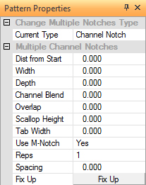
Change Multiple Notches Type |
|
|
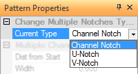
Current Type |
This field displays the current notch type. You can double-click the field label to toggle through the notch types or select the desired type from the drop-down list. |
|
Multiple Channel Notches |
|
|
Distance from Start |
This value is derived from the start point at the beginning of the selected line. You may type the value or use the mouse to specify the value. |
|
Width |
The width of the notch. |
|
Depth |
The depth of the notch. |
|
Channel Blend |
This option allows you to specify an arc radius value for the corners of the Channel Notch. |
|
Overlap |
This field allows you to control the distance between tool hits by specifying the amount of overlap. |
|
Scallop Height |
Use this field to control the scallop height on a specific angle. The scallop height is the distance formed by the scallop of nibbling tools. |
|
Tab Width |
You can specify a positive or negative tab on the width of the notch. |
|
Use M-Notch |
If you want multiple notches, activate the Use M-Notch drop-down list and select Yes. If you only want one instance of the notch, select No. |
|
Reps |
The number of repetitions (copies) of the notch. |
|
Spacing |
The spacing between each notch. |
|
Fix Up |
Click Fix Up after placing the notch or notches to remove the unnecessary lines. |
 |
Option |
Description |
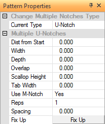
Change Multiple Notches Type |
|
|
Current Type |
This field displays the current notch type. You can double-click the field label to toggle through the notch types or select the desired type from the drop-down list. |
|
Multiple U-Notches |
|
|
Distance from Start |
This value is derived from the start point at the beginning of the selected line. You may type the value or use the mouse to specify the value. |
|
Width |
The width of the notch. |
|
Depth |
The depth of the notch. |
|
Overlap |
This field allows you to control the distance between tool hits by specifying the amount of overlap. |
|
Scallop Height |
Use this field to control the scallop height on a specific angle. The scallop height is the distance formed by the scallop of nibbling tools. |
|
Tab Width |
You can specify a positive or negative tab on the width of the notch. |
|
Use M-Notch |
If you want multiple notches, activate the Use M-Notch drop-down list and select Yes. If you only want one instance of the notch, select No. |
|
Reps |
The number of repetitions (copies) of the notch. |
|
Spacing |
The spacing between each notch. |
|
Fix Up |
Click Fix Up after placing the notch or notches to remove the unnecessary lines. |
 |
Option |
Description |
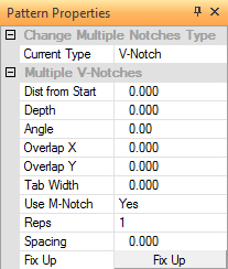
Change Multiple Notches Type |
|
|
Current Type |
This field displays the current notch type. You can double-click the field label to toggle through the notch types or select the desired type from the drop-down list. |
|
Multiple V-Notches |
|
|
Distance from Start |
This value is derived from the start point at the beginning of the selected line. You may type the value or use the mouse to specify the value. |
|
Depth |
The depth of the notch. |
|
Angle |
This value is used to adjust the angle of the V-Notch. |
|
Overlap X |
This field allows you to control the distance between tool hits in the X direction by specifying the amount of overlap. |
|
Overlap Y |
This field allows you to control the distance between tool hits in the Y direction by specify the amount of overlap. |
|
Tab Width |
You can specify a positive or negative tab on the width of the notch. |
|
Use M-Notch |
If you want multiple notches, activate the Use M-Notch drop-down list and select Yes. If you only want one instance of the notch, select No. |
|
Reps |
The number of repetitions (copies) of the notch. |
|
Spacing |
The spacing between each notch. |
|
Fix Up |
Click Fix Up after placing the notch or notches to remove the unnecessary lines. |