![]()
When Load Parts, Machine and Settings are configured, click the Start Nesting button to begin the actual nesting process. Keep in mind that clicking Nesting always nests parts directly from the Parts List for Nesting. If a job that has been nested is being edited in the Edit Layout panel, any changes made will be lost if the user clicks Start Nesting again.
Notes:
Be sure to verify that entries in the Parts List for Nesting correspond
with actual materials available in the Material Library (pay special attention
to material type, thickness, sheet size, coating, etc.) If there's a discrepancy,
the nesting will fail.
When the Start Nesting button is clicked, the program will first group
parts with the same material type, thickness,material file name and coating
into one schedule to nest. After nesting the schedule name will become
the Job Name with endings such as -S1, S2 added to the name to distinguish
more than one schedule in a job.

While Sheet Wizard is processing the nesting, above image will appear and rotate at the center of the screen.
Also in this section:
If Method A has been selected in the Settings>Sheet Layout section, and the Start Nesting button is clicked, the program will put the nesting operation on hold and launch the Choosing Nesting Results window shown here.
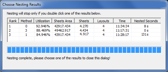
AP100US automatically calculates various nesting result options, from which the user may select. Double-click a row to close the window and resume the nesting operation that will give the results shown in the row.
The user may make a selection from the available Nesting Methods (shown in the second column) that were generated.
See Nesting Strategies for an explanation of the values in the Method column.
Note: The Choose Nesting Results dialog by default is switched ON in the C:\AP100US\Parm>NestWizard.ini file. It may be switched OFF if desired.
If certain parts did not successfully nest in the current nesting job, the name, size and quantity of the failed part(s) will display in a table in this window. If no part failed to nest in the current job, this window will not display.
Note: Parts that fail to be nested become like leftover parts that remain in the Load Parts panel, where they can be edited or deleted.
Option |
Description
|
|
Click the Back Arrow to return to the main Sheet Wizard window. If NC code has already been generated for the job, hitting the Back arrow will erase the code. |
|
Click the Forward Arrow to advance to the next Window. When the NC code has been generated hit this button to finalize the job. This will allow various report files to be generated, and push the job info to other destinations such as the Job List.
|
|
Click the Square to cancel the nesting operation and return to the main AP100US interface. (Nesting that has been completed up to this point will be visible in the AP100US work area.) |
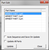
If problems occur in the current nesting job, the system will launch this preview window listing the problems. If no problems occurred in the current job, this window will not display. There are four types of problems that are previewed in this window: Part(s) without Microjoints/Tab; Part(s) with missing tool assignment; Tool interference inside part(s); Interference Between Parts. |
Double click on any part listed to open and edit the part in the main AP100US interface. Once the edit is complete, return to the Problems Encountered Window by clicking Update (to save any changes) or Close, which is available in this floating dialog box that hovers over the main work area - |
Note: Parts that have been imported in part kits (or groups) are "as is." That is, a part or parts from a part kit may not be opened and edited in the AP100US work area through the Sheet Wizard module. If it is necessary to edit parts from kits (such as adding microjoints) the kit must be opened separately on a sheet in AP100US, saved and then reloaded into the Sheet Wizard. |
Option |
Description
|
Check Interference Between Parts |
Click to check for any interference between parts. Note: The Sheet Wizard program only takes into account part geometry. There may still be interference between parts in the CAM because of tool assignment, or other CAM attribute features.
|
Always check automatically |
Check this box to enable the program to always automatically check for interference between parts. |
After problems are resolved in the Problems Encountered window, click the Next Arrow and when nesting is completed, the Results Window will appear.
|
To push a fully prepared job to the Schedule List click the Commit button. The job must first be saved or the Schedule List won't accept it; the job should also be sequenced, as without the NC code a job cannot be processed on a machine. Be sure to use a unique name for each job committed to the Schedule List. Jobs in the Schedule List are considered to be "active" and are waiting to be (or have already been) pushed into production. Note:
A job is one or more sheets that have been fully prepared and
sequenced in either AP100US or Sheet Wizard and is ready to be
sent to the shop floor. |
|
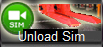
Select this button to see an unloading simulation utilizing Part Removers in the Automatic Simulation Module. When the module opens select the file name (with the date stamp when the project was nested) in the program panel on the left to run the simulation. See Automation Simulator for more info. Note: This feature is not available for older machines and drivers.
|
|
Select this button to open the Part Stacker Module to arrange parts as they will be placed when they are unloaded to the stacking table. When the module opens the current sheet will display in the Part Stacker work area. If it does not display, go to File>Open to manually load the sheet file. See Part Stacker Module for more info. Note: This feature is not available for older machines and drivers. |
|
Click the button to save the Schedule output from Sheet Wizard to an SDDJ server that was selected during the AP100US installation/update, or to a file so it can be available for use by the AMNC-IT. If an SDDJ server was not selected during product installation, or the SDDJ server does not exist, the user may still save the schedule to a file. See also Save Schedule to SDDJ for more info.
|
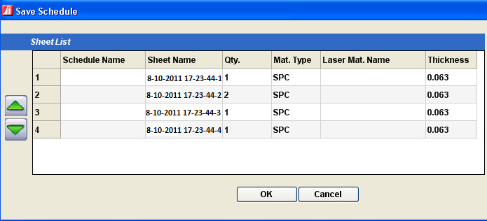
When the user clicks the Save Schedule to SDDJ button, the Save Schedule dialog will display as shown here -
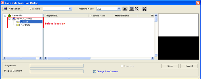
Users may re-arrange the schedule in the Save Schedule dialog, and change the sheet sequence, quantity and so on. SDDJ doesn't support special characters like *, ?, < or > and has a string length limitation of 20 characters. If the job name cannot be used by SDDJ, a dialog will display allowing the user modify it before going to the Save Schedule dialog. After clicking the OK button to save the schedule, the Avon Data Insertion Dialog will display as shown here -
In this dialog, the user must select a location in the left panel to save the schedule in SDDJ. The schedule will be stored into SDDJ after clicking the Save button. |
|
|
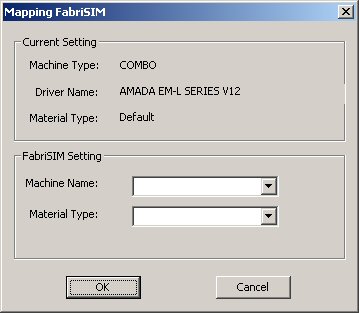
Click the FabriSIM Nesting Simulation button to view a simulation in FabriSIM. Note: FabriSIM must be installed to use this option. After clicking the FabriSIM button, the mapping dialog will display if the information hasn’t been mapped before -
Current Settings (read-only) The Machine Type, Driver Name and Material Type are the current AP100US types loaded into AP100US. FabriSIM Setting Select a Machine Name and Material Type from the pull-down menus, and then click OK to finish the integration with FabriSIM and launch the FabriSIM program automatically. Modify parameter settings in FabriSIM as needed. See FabriSIM documentation, which is found in theAP100US installed folder.
|
|
When the View Report button is clicked, a standard report of the currently selected sheet will display in a browser. Label
Part Names If the Output Report is switched OFF in the Settings>Report Settings panel and the Output FastReport is switched ON, when this button is selected the FastReport will display. To have a report generated Output Report must be ON. Based on selections made in the Report Setting pane, either one report for all sheets or separate reports for each sheet will be viewable. |
|
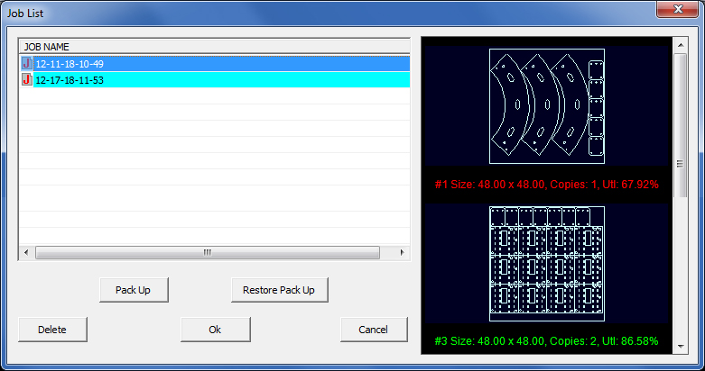
Click the Job List button to open a dialog listing archived jobs. Jobs in this list may still be pulled into the Sheet Wizard, edited and pushed into production.
Click Pack Up to pack up all files relating to the current job in a zip file and send them to the C:\AP100US\SupportFiles folder. From there the user may share the file with a colleague or to Amada Support for assistance. See The Help Menu for more info. Restore Pack Up opens the same folder and allows the user to restore an older file to the Sheet Wizard. With this option the user can select any number of files to open. Select a Job and then click Delete to permanently delete that file from the directory. Select a file and click OK to open it in the Sheet Wizard. Cancel closes the dialog without making any changes. Note: The details for sheets may appear in green or red. Green signifies a normally sequenced sheet with NC code; red signifies that sequencing and NC code were not processed. See Sheet Status below for more info.
|
|
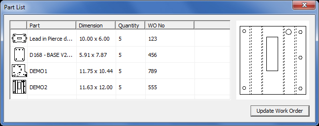
The work order number, provided during processing, can be edited by users with job tracking software/hardware systems such as ERP and MRP. If a WO No is edited it can be updated to the work order itself by clicking Update Work Order. When re-using an existing order for repeat orders, the user can enter a new unique Work Order No by entering text directly into the WO No text cell.
|
Column |
Description
|
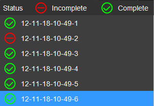
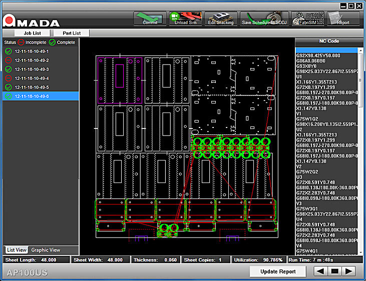
Sheet Status
|
The system lists all the sheets generated during nesting. Select a sheet file name to view the sheet in the preview pane and view its NC code. In the List View tab, sheets are listed by name. A sheet marked with a green checkmark means that sequencing went normally, the NC code was generated and the sheet is ready to go. A sheet with a red mark means that NC code generation was most likely switched OFF for this sheet and was not generated. (See Settings>Sequence Settings for more info on this.) . In the Graphic View tab view thumbnail images with basic info for each sheet.
Delete a sheet - Right-click on any sheet listed and click Delete to remove it from the current job. The user may also select multiple files for deletion using standard Windows shortcut keys. When a sheet or sheets are "deleted" in this way, they will be returned to the Parts List for Nesting. This allows the user to process the sheet(s) again in another job if desired. When a user removes a sheet in this manner, any reports connected to the current job will also be updated according to the change.
|
Sheet Preview
|
The Sheet Preview pane in the center shows the currently selected sequenced sheet file. Scroll with the mouse wheel to zoom in and out, and hold the mouse wheel down to drag the sheet image. Note: To enable this feature, Show Tool Hits and Show Sequence must be selected in the Preferences > Display Options panel. If the nesting results are not satisfactory, double-click the Sheet Preview panel to go to the AP100US interface and edit the sheet file. See Edit Layout>Editing a Sheet in the AP100US Work Area for more info.
|
NC Code
|
The NC Code for the current project is displayed in this read-only panel. When the user clicks on any line of code in this panel, it will highlight the corresponding sequence in the sheet shown in the Sheet Preview pane. Note: When the NC Code is generated, the system will NOT prompt the user to enter extra information such as Part Number, Customer Name or Programmer Name. Such information should be preset in Part Info or Sheet Info. Other fields will be left empty by the system. Directories of Generated Files When NC code is generated various files (such as .xml, part.jpg, sheet.jpg and Barcode report) are saved to the Reports folder in the AP100US installed folder. NC and SY2 files that are generated are still saved to the NC Files folder. |

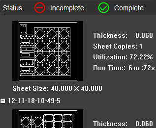
AT the bottom of the window, Sheet size, Sheet Thickness, Sheet Quantity, Sheet Utilization and Run Time are displayed for the currently selected sheet.
If Run Time
does not display, click on the Run Time clock - ![]() .
For a run time to display a jka (or other jk...) file must be loaded.
.
For a run time to display a jka (or other jk...) file must be loaded.
(See Machine Information>Description Panel>Condition File for more info.)

Hitting Update Report will update any recent changes made to the sheets and allow the thumbnail images of the sheet to be included in the report. This button only appears when Multiple Sheet Report is checked ON and there is more than one sheet in the project.