To view information and make changes to the currently loaded sheet, select Sheet Info from the File menu, or click the Sheet Info button on the Amada A file menu. This opens the Sheet Information dialog.
Note: The program must be in Sheet Mode for the button to be active.
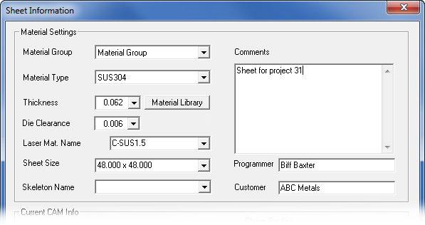
The Sheet Information dialog box allows the user to set properties for the sheet, before parts are added. Any values entered are used by the program to adjust settings such as Nibble Pitch, Auto Tool Selection, Reposition Distance and other values.
Material Settings
Material Group
Select a Material Group name. The new Material Group as well as previous
Material Groups appear in the list and can be selected. When saving the
sheet file, the Material Group will be saved also
Material Type
Select a Material Type name from the list. Any material type that appears
in the list can be selected.
Once a material type has been selected the Sheet Thickness and Material File (Under Current CAM Settings) will update reflecting the data for that material type.
The Sheet size will default to 48.000 x 48.000 but the drop-down box will display the sizes currently associated with that type. When saving the sheet file, the Material Type will be saved also
Thickness
The thickness of the selected material type will be displayed in this text
box if a material type has been selected. A different thickness
can also be input here.
Material Library Button
Click to open the Material Library, which allows the user to Add, Delete
and Modify material settings. Selecting a material from this interface
will update the Material Group, Material Type, Thickness, Sheet Size and
Laser Material Name.
For more information see Material Library.
Die Clearances
This is the Die Clearance that was assigned to the tool. If more
than one Die Clearance was assigned, the user may select a different Clearance
by clicking in the field and selecting a different die from the pull-down
menu. See ATC - Select Die Clearance
for more info.
Laser Material Name
From the drop-down, select a laser material. This field is only active
if a laser machine and .jka (or
other .jk... file) is loaded.
Sheet Size
Enter a custom size to create a new sheet or choose a sheet size from the
drop-down list. Sheet Sizes will be listed based on the selected Material
Type.
Skeleton Name
A skeleton sheet may be selected from the pull-down list. Skeleton sheet
creation is enabled in the Machine
Settings>Sheet Layout panel while the sheet itself is generated
in the Sheet Wizard and stored in the Material Library.
See Material Library>Material Type Editing Options>Skeleton Sheet for more info.
Comments
This text box allows optional sheet comments to be entered. Any comments
are passed to the driver and output in the Set-Up Sheet section of the
NC code.
Programmer/Customer
These fields allow programmer and customer names to be entered. A programmer
or customer name in the text box will be saved with the sheet file, passed
to the driver and output in the Set-up Sheet section of the NC code.
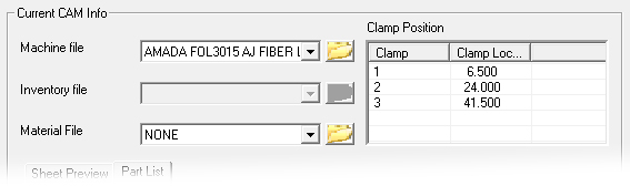
Current CAM Information
Machine File
If the clear database option is checked, this field displays the
Default Machine Name set in Preferences. If the clear database option
is unchecked it will display the current machine.
A different machine file can be selected from the drop down if available.
![]() The
folder icon allows the user to browse to a new folder location for Machine,
Inventory & Material files.
The
folder icon allows the user to browse to a new folder location for Machine,
Inventory & Material files.
Inventory File
Displays the tool inventory that is associated with the Machine. A different
tool inventory file can be selected from the drop down if available.
![]() The
folder icon allows the user to browse to a new folder location for Machine,
Inventory & Material files
The
folder icon allows the user to browse to a new folder location for Machine,
Inventory & Material files
Material File
Displays the material file that is associated with the machine file. A
different material file can be selected from the drop down if available.
![]() The
folder icon allows the user to browse to a new folder location for Machine,
Inventory & Material files
The
folder icon allows the user to browse to a new folder location for Machine,
Inventory & Material files
Clamp Position
This read-only list displays the initial clamp locations, which are based
upon the sheet size
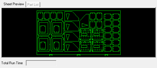
Sheet
Preview / Part List tabs
The Sheet Preview gives a thumbnail
preview of the current sheet as shown here -
Part List (shown here) allows the user to view parts on an order on the AMNC-IT computer, so the work order can be output in reports and SY2 files. When re-using an existing order for repeat orders, the user can enter a unique Work Order No directly into the cell.
Also enter an alphanumeric Part Revision code if desired; such an entry will be synchronized with the same cell in the Sheet Properties panel. The read-only revision code also displays in the Sheet Wizard>Edit Layout panel.
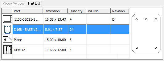
Only WO No & Revision can be edited here
Total Run Time
After the NC Code has been generated and Run Time calculated, the run time
for the sheet will display in this read-only text box.
Once calculated and new changes are made, the run time will not update automatically.
See View Run Time for
more information.
Function Buttons
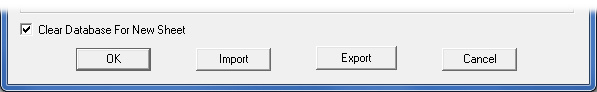
Clear
Database for New Sheet
This checkbox only displays when the Sheet Information dialog has been
opened by clicking the New Sheet
icon on the Quick Access Toolbar,
or selecting New Sheet from the Main
(File) menu.
The Clear Database For New Sheet checkbox is only used when creating an entirely new sheet.
If a check mark is placed in the check box, the program will clear the database of all sheet information. This includes the parts and the defaults that have been set, and the system preferences that display in the Current CAM Info fields.
(See File>Part Info>CAM Information for more details.)
If the database is NOT cleared (box is unchecked), the program will preserve the current Machine name, Material File, and Tool Inventory. It also retains all of the parts and their current locations.
Note: Whether the box is checked or unchecked, the fields in the Current CAM Info and Material Library may still be modified. These settings are applied only when the user selects the OK button
OK/Cancel
Click OK to save any changes and close the dialog. Click Cancel
to close the dialog without saving any changes.
Import
Clicking the Import button displays the Open>Parts dialog box.
In addition to standard inv files, the user may choose to load from Tool Inventory files in .XLS or .CSV formats. From here it is also possible to create and edit .xls and .csv files. See Export below for more info on this
Export
To export Tool files in .XLS or .CSV formats, click Export.
The Save As dialog will open allowing the user to save directly to the
TOOLINV folder in the AP100US installed folder in either .xls or .csv
format.
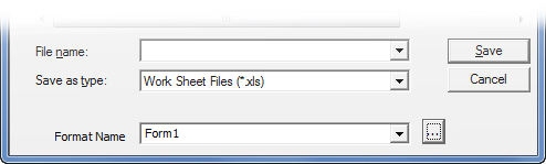
The Save As folder contains a Format Name and button. The user may select from existing formats, or click the button to open the Format Options window to create or edit formats.
See Exporting Files in XLS or CSV formats in the Material Files folder for more info on creating and editing .xls and .csv files.