![]() Use
the Grid option to grid a part manually in the X and Y direction.
Use
the Grid option to grid a part manually in the X and Y direction.
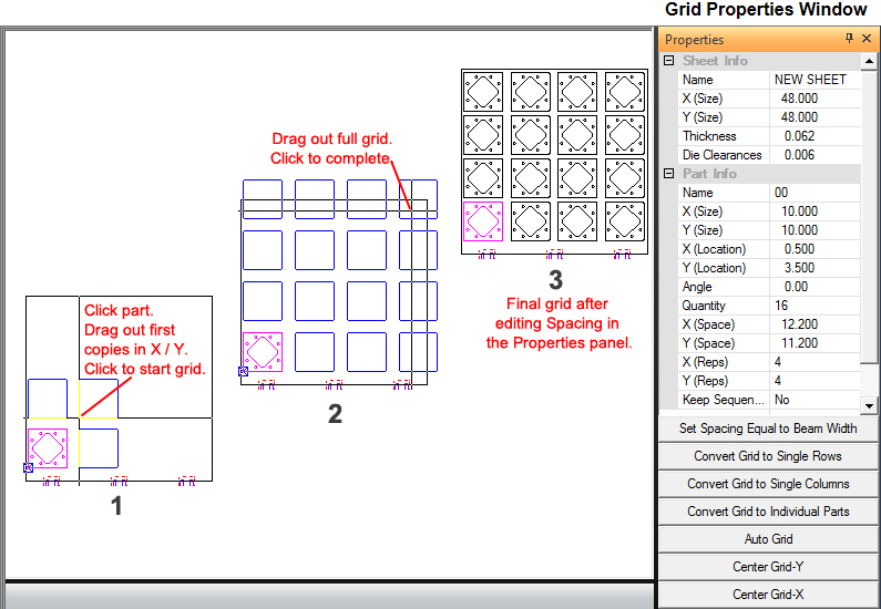
Select Grid from the Sheet menu and click the crosshair over the part to be gridded and click. 1) Drag out the first copies in X / Y and click to start the grid and confirm grid parameters. 2) Drag out the grid to the upper right corner to fill the sheet with parts and click to complete the grid. 3) In the Grid Properties Window make adjustments to the grid as needed.
Notes: Use the Grid option to modify an existing grid. Select the option, move the crosshair into the work area and click any part within the grid. The Grid property window will appear and the part boxes begin to follow the pointer.
If you want to use subroutines, you must create a grid. You will learn more about Start Subroutines, Grid X and Grid Y when you start sequencing.
|
|
Option |
Description |
Sheet Information |
|
Name |
The file name of the sheet. |
X (Size) |
The X dimension of the sheet. |
Y (Size) |
The Y dimension of the sheet. |
Thickness |
The thickness of the material. |
Die Clearance |
This is the Die Clearance that was assigned to the tool. If more than one Die Clearance was assigned, the user may select a different Clearance by clicking in the field and selecting a different die from the pull-down menu. See ATC - Select Die Clearance for more info. |
Part Information |
|
Name |
The file name of the part. |
X (Size) |
The X dimension of the part. |
Y (Size) |
The Y dimension of the part. |
X (Location) |
The X coordinate of the original part’s reference point. |
Y (Location) |
The Y coordinate of the original part’s reference point. |
Angle |
The angle of the part. |
Num |
The total number of parts within the grid. |
X (Space) |
The horizontal spacing for a gridded part. The horizontal spacing is measured from the part’s origin (lower left corner) to the origin of the first copy to the left or right. |
Y (Space) |
The vertical spacing for a gridded part. The vertical spacing is measured up or down from the original part’s origin to the first vertical copy. |
|
Note:The values should be the part size and the amount you want between parts.. If you want to overlap the boundaries, you must specify a values for the X and Y spacing. |
X (Reps) |
The number of horizontal repetitions for the part. |
Y (Reps) |
The number of vertical repetitions for the part. |
Keep Sequence |
This option allows you to maintain any sequencing after you modify the grid. The option is only available if you have enabled the Subroutine options in the Sequence Info panel of the Machine Setup Window. |
Set Spacing Equal to Beam Width |
This option is available in the property window if you have loaded a cutting or combination machine. If you select this option, the system will adjust the grid spacing between parts to equal the beam width (as specified in the material file). |
Convert Grid to Single Rows |
This option divides a grid of parts into horizontal row grids. |
Convert Grid to Single Columns |
This option divides a grid of parts into vertical row columns. |
Convert Grid to Individual Parts |
This option allows you to convert a grid into individual parts. Selecting this option will reset the sequencing. |
Auto Grid |
Click this button to switch to Auto Grid mode. The Auto Grid Properties window will appear. |
Center Grid Y |
This option will center the grid along the Y-axis. |
Center Grid X |
This option will center the grid along the X-axis. |