Manual Perimeter Notch Relief Functions
When using automated part removal systems, there may be perimeter "notches" or cutouts that make it very difficult for an automation arm to successfully remove the part from the sheet. To solve this issue, additional cuts need to be made to free up areas of the part that can "catch" when the automatic part remover attempts to remove the part.
To automatically apply simple Notch Cut Outs to notches on a part according to size, see Notch Cut Out Range below.
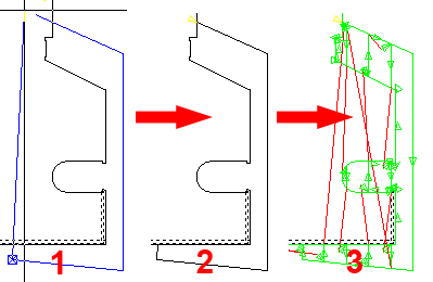
This diagram shows the basic process - Step #1, the user draws a box (in this case a Fence Select) around a problem area. Step #2 shows the finished box. Step #3 - After the part has been sequenced, this shows the notch that will be destroyed according to user-selected settings.
Perimeter Notch Relief Menu Options in the User Interface
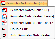
The Perimeter Notch Relief (RE) function found in the Sequence Features menu allows the user to drag out a standard rectangle by left-clicking in the most convenient corner, and then dragging to the opposite corner and clicking again to finalize.
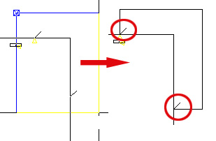
In this diagram the lead in and lead out are circled in red.
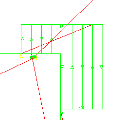
The Fence option (shown in the first illustration at the top of this page) allows the user to left-click as often as necessary to set coordinates for the fence. When the final point has been placed, the user must right-click to close the fence and then left-click again to finalize.
To delete a Perimeter Notch Relief, select Notch Relief Delete, place the crosshair over the Relief and left-click once. The user may also click the Clear Attributes button in the Sequence Features menu, select Notch Relief and click OK. Using this option will delete ALL Notch Reliefs and Double Cutting on a part.
![]()
Notes:
The part's normal profile (closed loop) CAM will remain unaffected when
using this option.
The Notch Relief Cuts will, by default, be sequenced before the outer profile.
The part's Snap Points can be used, if desired by user, to help define
the Notch Rectangular area.
The resulting Laser Relief Cut (CAM) and any Slug Destroy Cuts will be
adjusted to reflect beam width (if Cutter Compensation is active).
Settings for Perimeter Notch Relief
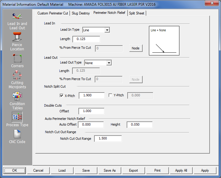
To input settings for Perimeter Notch Reliefs (found on the Sequence Features menu), go to the Material Info>Process Type window, and click open the Perimeter Notch Reliefs tab.
Lead In / Lead Out
Enter Lead in and/or Lead out settings that take effect only when Perimeter Notch Relief is applied to the part.
Lead In
Choose between Line
to enable lead-ins on cuts between parts on the sheet and None to disable lead-ins.
Length
Enter the length of lead-ins. Choose values that will not allow lead-ins
to cut across the face of the part or adjacent parts.
Note: The system will calculate angle based on the type of Perimeter Notch used (i.e., box or fence) and its placement on the part.
% From Pierce to Cut / Node
When the user presses the Node button the Cutting Condition dialog opens,
allowing the user to select cutting conditions. In the % From Pierce to
Cut field enter a value (given in a percentage from the Start Point) for
the location of the node.
Lead Out
Lead-outs are applied in a similar manner.
For full information on the use of these types of options, see the
Lead In and Lead Out panel.
Notch Split Cut
Enter split values in X and Y to destroy external notches. Part must be sequenced for Cuts to take effect. Values entered here are synchronized to the Common Cutting Settings>Notch Split Cuts values in the Common Cutting Settings submenu and saved into the material file.
Note: For slug destroy used elsewhere (that is, outside of Common Cutting) only the Y pitch value will be used for split cuts in both X and Y.
External notch is destroyed
Double Cuts
Enabling Double Cuts causes the machine to cut along the new edge. This can give a cleaner edge and make it easier for the part to be removed because it creates a wider gap. To enable Double Cuts set a Double Cuts Offset value in the Takeout Reliefs tab. A previously assigned Double Cut must be deleted before a new Double Cut (with a different Offset value) can be assigned.
Note: Setting Double Cuts on a part may interfere with Perimeter Notch Reliefs.
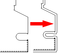
The part on the left before Double Cuts is enabled. The same part on the right with Double Cuts.
Auto Perimeter Notch Relief allows the software to independently select possible problem areas on the part and place Reliefs.
Enter Auto Offset and Height values in the fields to control the size of the notch (see image below right).
Note: Notch Cut Out Range (the next option) must have a value entered to enable this function.
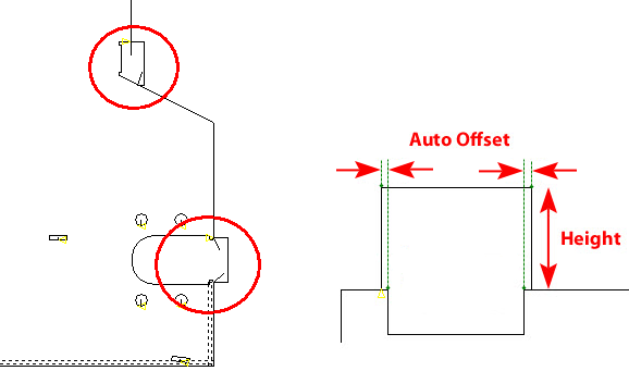
The Auto
Reliefs assigned by
the program are circled in red.
Note: When changes are made to notches that have been previously applied, Notch Relief does NOT update automatically. It may be necessary to clear and then add the notch relief again.
Notch Cut Out Range enables the user to add extra cuts to a cut sequence, in order to cut out notches from the perimeter of a part that may hinder the part remover.
Notch
Size
Enter a value in the Notch Cut Out Range
field to control the range (size) of cutouts that the system will apply
cutouts to. This will cut out notches with a size that is equal to or
less than the value entered in the field.
Auto
Assign Cutouts
The user may also auto-assign cutouts to notches. Hit the Process
Part button and all values entered in the Perimeter Notch Relief tab
will be applied to the part. A value must be entered in the Notch Cut
Out Range field to activate this option.
To disable this option, enter a 0 in the
field.
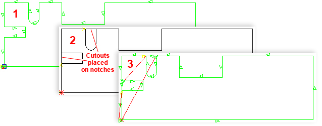
In image 1, a U Notch and two Box Notches have been added to the part perimeter and the part was sequenced. Notice that the notches have not been cut out and will remain attached to the skeleton.
In image 2 a value of 0.5 was entered into the Notch Cut Out Range field and then the user hit the Process Part button in the Cut Sequence tab. The two smaller notches are 0.5 in width, so the notch cutouts were added during processing. The larger notch will be ignored by the system.
Note: When the Notch Cut Out Range field is activated, all settings in the Perimeter Notch Relief tab (such as Lead In/Out) will be also be applied to the part.
Image 3 - When the part is sequenced after processing, the two smaller cutouts will be completely cut out of the sheet.