A punching condition is a machine operation that is assigned to a pattern. The options are driver dependent; the machine driver must support the condition. Punching conditions allow you to modify machining operations along the path. You should not confuse these particular conditions with those that you can assign to tools. When you assign punching conditions to tools, the conditions are implemented when the tools are called. See also Punching Conditions Dialog for more info on assigning punch conditions to tools.
Note: This option functions in Part View.
|
|
Punching condition nodes appear as square pixels and by default are yellow; however, the user can change them to any color in Preferences>Color & Style Parameters.
|
|
Options covered on this page are -
For info on Outputting a tapping tool to SDDJ when using the ATC Storage unit, see Adding Tools to the PDC/ATC.
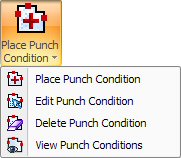
This option allows you to place punch conditions on the geometry. To begin the process, select Place Punch Condition from the Punch Condition submenu, or click the Place Punch Condition button on the Punch Feature toolbar to display the Punch Condition window.
Notes: Some punching conditions require values. If necessary, make sure to type a value in the field that appears below the drop-down list.
Punching conditions are always placed in the center of the geometry.
Punching conditions appear in the Tool Gouge/Cutting Attribute color you have selected in the Color Parameters panel of the Preferences window.
The options that appear in the Punch Condition window are dependent on the machine driver. These options must be customized for each driver.
The Punch Condition window appears after you select the Place Punch Condition option. The actual conditions supported by the currently loaded machine driver appear along the left while the drop-down list for each condition item appears along the right. For example, in the illustration below, the Before option was selected for INPUT DWELL VALUE and a pause value specified in the field immediately below the drop-down list.
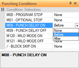
To define a punching condition for a path, move into the Punch Condition flyout window and select either Before, After or None from the drop-down list that follows the descriptive label. If you select Before, the condition occurs before the pattern is sequenced. If you select After, the condition occurs after the pattern is sequenced. The default selection is None.
This option allows you to view or modify an existing punching condition. Select Edit Punch Condition from the Punch Condition submenu. The pointer bounces among any existing punching condition nodes. Move the pointer onto a node and click the left mouse button. The Punch Condition window updates and will display the condition(s) currently assigned to the geometry. You can then modify the conditions by making the appropriate selections from the drop-down lists.
Select Delete Punch Condition from the Punch Condition submenu to remove any punching conditions you have assigned to the geometry. The pointer bounces among the existing nodes when you move into the work area. To delete a punch condition, move the pointer onto the condition node and click the left mouse button.
To see all the punch conditions placed on the part or sheet, select View from the Punch Condition submenu. If you want to see the punch microjoints during each redraw of the work area, make sure a check mark appears in the Show Features check box under Sequence Information in the Display Options panel of the Preferences window.
