The Hatch Etching option on the Sequence Features tab allows the user to create decorative designs and text on a part by etching out specified surface areas in a pattern.
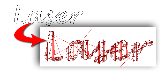
The brown lines show where the laser is etching,
while the
red lines show laser head movement between etchings
How it works
The user must first draw patterns and/or add text to the part. See Draw / Edit for patterns and Etch Options (under Sequence Features) for text.
Be sure that Show Cutting Direction is enabled in Preferences>Display Options.
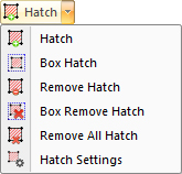
On the Sequence Features tab, click Hatch to display the pull-down menu.
Select Hatch and then click on a pattern to apply the hatch etch. After sequencing (see the Cut Sequence tab) the hatch etching on the pattern is visible as in this image -
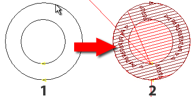
In image #1
the user has selected the outer round pattern. Image
#2 shows
that after sequencing only the area in the outer round has been hatch etched
(etch
lines shown in brown). The red lines in the inner round show laser head
movement.
Box Hatch
The user may drag out a box around patterns that are to be hatch etched. To do so, left-click on one corner of the group of patterns to be etched and drag the box out to the opposite corner, left-clicking again to finalize.
Click Remove Hatch and then select a pattern to delete hatching on that pattern. Use Box Remove Hatch to drag out a box around specific hatch lines that are to be deleted (Hatch lines must be selected completely and removed completely; selecting half a hatch line is not possible.). Selecting Remove All Hatch deletes hatch etching on all patterns. (When in part view it clears all hatch etching on the current part. In sheet view it clears all hatch etching on each part on the sheet.)
Note: When making changes to hatching, re-sequence the part/sheet to see the result.
Adjusting Settings
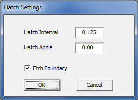
The user may adjust hatch etch properties at any time. To do so click Hatch Settings -
In image #1 below, Hatch Interval was set to 0.2, Angle to 0 and Etch Boundary was checked ON (the default setting).
In image #2 Interval was 0.1, Angle - 15 and Etch Boundary checked OFF. The red arrows indicate the areas of the pattern boundary that were NOT etched.
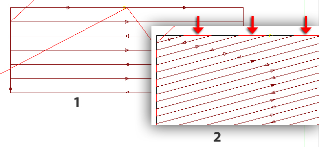
Using Etch Boundary in most cases may give the hatch lines on a pattern a smoother outer perimeter. However, Etch Boundary may be switched OFF as needed.
Note: Oxygen as assist gas makes the etched area darker, whereas nitrogen as an assist gas makes it somewhat lighter. The depth of the etch cannot be controlled in AP100US; the machine operator must edit this setting on the machine control console.
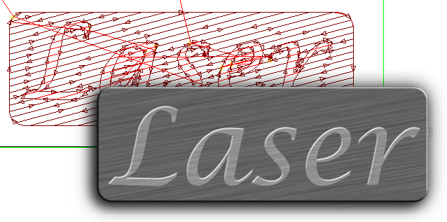
A Working Example
The text "Laser" was placed on the part and a rectangle with rounded corners was then drawn around the text. The cutouts in both the "a" and "e" and the outer perimeter were all selected for hatch etching. The final part after processing in a laser machine would be similar to the image at bottom; the text "Laser" appears to be raised because the background has been etched out.