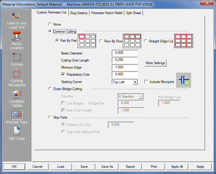
The Process Type>Custom Perimeter Cut tab contains options that allow you to specify what process the system uses to cut the parts. Specify None (default), Common Cutting, Chain/Bridge Cutting or Skip Parts parameters.
See information on the Split Cutouts, Perimeter Notch Relief and Split Sheet options.
The four options in the Custom Perimeter Cut section allow you to select the preferred cutting method for the part boundaries. Your choices are None, Chain/Bridge Cutting, Common Cutting and Skip Parts.
None |
None is the default selection. The system cuts the part boundaries using the cutting direction, CW or CCW, selected for the Outside Parameter in the Pierce Location panel. |
Common Cutting |
If you select this option, the system cuts the part boundaries using the specified parameters in the Common Cutting Information section. |
Chain/Bridge Cutting |
If you select this option, the system cuts the part boundaries using the specified parameters in the Chain/Bridge Information section. |
Skip Parts |
If you select this option, the system cuts the part boundaries in an order or sequence using the specified parameters in the Skip Parts Information section. |
The options in the Common Cutting Information section allow you to specify the parameters for common cutting. The following table describes each option. (See Common Cutting Module in Cut Sequence for more info.)
Common Cutting Method |
Use the options in this section to specify the preferred cutting method.
|
Part By Part |
Select Part By Part if you want common cutting to sequence one part before continuing onto the next part. When this option is selected, Bottom Left and Bottom Right options will be added to the Starting Corner settings.
|
Row By Row |
Select Row By Row if you want common cutting to sequence a complete row of parts before processes the next row.
|
Straight Edge Cut |
Used primarily for automation, selecting Straight Edge Cut allows the AP100US system to automatically detect and cut out perimeter notches first, before common cutting the overall part/group boundaries. Note: When this option is selected, the Cutting Over Length, Minimum Edge and Preparatory Cuts selections are disabled. See Common Cutting Settings for more options.
|
Beam Diameter |
Use this field to specify the default beam width used during common cutting mode. Note: The Beam Diameter input text box is dynamically linked to the same text box in the Pierce Location panel>Cutter Compensation section. Updating the value in one of these fields, updates both accordingly.
|
Cutting Over Length |
Type the amount the system should overcut before starting or after ending a closed path.
|
Minimum Edge |
Type the minimum distance that must be shared before the software will use preparatory cuts.
|
Preparatory Cuts |
If you enable this option and type a length value in the text box to the right, the system sequences a series of preparatory cuts along the part perimeters. The system cuts the specified length of the adjacent part perimeter before processing the remainder of the boundary.
|
Starting Corner |
The four options you can select from this list allow you to specify the start of the common cutting. Select either Top Left, Top Right, Bottom Left or Bottom Right. |
|
Top Left Common cutting begins in the top left corner of the sheet. |
|
Top Right Common cutting begins in the top right corner of the sheet. |
|
Bottom Left This option appears if you select Part By Part under Common Cutting Method. The common cutting begins in the lower left corner of the sheet. |
|
Bottom Right This option appears if you select Part By Part under Common Cutting Method. The common cutting begins in the lower right corner of the sheet.
|
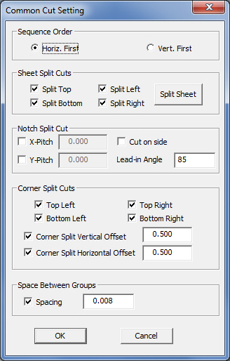
More Settings |
Click this button opens a smaller version of the Common Cutting Settings window. Both windows are synchronized. See Common Cutting Settings for full info.
|
|
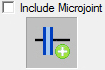
Place a check in the box in order to enable the program to allow microjoints between parts during Common Cutting. Click the Microjoint icon to open a dialog with further options. Note: Enabling microjoints on a Common Cut will not apply lead-ins or lead-outs automatically; the user must enable them separately. Lead-ins/outs must be applied carefully, as there is a risk that they will cut into an adjacent part. See Common Cutting Settings>Include Microjoint for more info.
|
Chain Cutting pierces the sheet once and then uses one continuous cut to process all the part profiles. The laser cuts from part to part and does not stop until the last part perimeter is completely cut out. However, the system only cuts a portion of the perimeter and completes the cutting later in the sequence. The system ignores any lead-out types applied to the perimeter cuts and must first cut the internal geometry of the parts. The length of the line lead-in at the starting corner is derived from the Length value specified in the Lead-In Type panel for External Geometry. Chain cutting can begin after the system processes the internal patterns.
1. Chain cutting processes both gridded and non-gridded parts.
2. Each grid should be less than the travel zone.
3. Only part boundaries are chain cut. Holes within the part perimeter are cut using a sequence that is similar to Common Cutting.
4. You cannot chain cut if the sheet contains parts inside of parts.
5. The gap between the parts should be greater than twice the beam width.
6. Four key points are used for possible switching between parts and placing bridge microjoints (left, right, top and bottom).
7. The chain cutting process overwrites microjoints and condition nodes on the part perimeters.
8. Patterns that you create in Sheet view are not included in the processing function of chain or common cutting.
The Cutting Direction (CW or CCW) you selected for the Outside Perimeter, and the selected Direction (X Direction or Y Direction) in the Chain/Bridge Information section determines the starting corner for the chain cut. See the following illustrations:
|
|
X Direction |
X Direction |
Part Perimeter Clockwise (CW) |
Part Perimeter Counter-Clockwise (CCW) |
|
|
Y Direction |
Y Direction |
Part Perimeter Clockwise (CW) |
Part Perimeter Counter-Clockwise (CCW) |
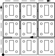
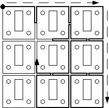
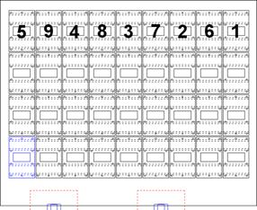
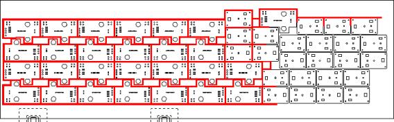
The system makes the pierce and then continuously cuts until all the parts are processed. The first direction of the cut is the opposite of the selected direction. The system uses the opposite direction to prevent interference and to return to the original part to complete cutting it. The illustration below depicts a sheet with a CCW (counter-clockwise) Cutting Direction set for the Part Perimeter and Y Direction selected for the chain cut:
The system starts cutting the part in the correct corner. The pierce is made either at the center of the part or the corner. When the system completes the first row of cutting, it cuts the remainder of the sheet in the selected direction. The system will only cut half the part before moving onto the next part. The system uses the mid-point of the common sides to determine the location of the next cut. The system will then cut to the next part and continue in the same direction. The process continues until the system reaches the end of the sheet. Once the system reaches the end of the first direction, it continues to cut in the selected direction.
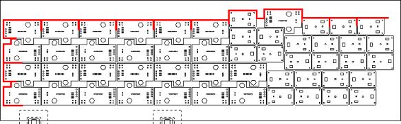
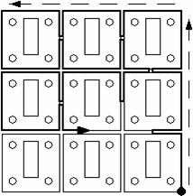
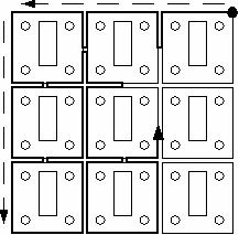
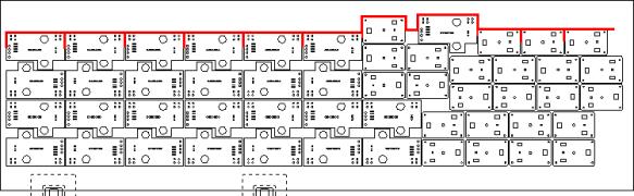
The illustration depicts the path the system moves in the vertical direction using the same rules. The system only cuts a portion of the part and will cut to the next part when it arrives at the mid-point of the common sides. The same rules apply until the system chain cuts the last part. The same rules are in effect for nested parts. The illustration below depicts the sequence when the system processes dissimilar parts.
Option |
Description |
Direction |
There are two options you can select from the drop-down list: X Direction and Y Direction.
|
X Direction |
Select X Direction from the drop-down list to specify the chain/bridge cutting along the horizontal axis.
|
Y Direction |
Select Y Direction from the drop-down list to specify chain/bridge cutting along the vertical axis.
|
Use Bridges |
Use the options in this section to define bridge sizes and lengths. Place a check mark in the check box to activate the Bridge Size and Max. Bridge Size text boxes.
|
Bridge Size |
Type a value in the text box to define the size of the bridge. See Bridge Cut.
|
Max. Bridge Size |
Type a value in the text box to define the maximum distance between parts allowed for bridge cutting. See Bridge Cut.
|
Max. Chain Length |
Type a value in the text box to specify whether parts are included in the chain cut range. See Bridge Cut. |
The Bridge Cut is similar to the Chain Cut; the same rules apply. However, the option tabs all the parts together using bridges (bridge microjoints). You must specify the Bridge Size and Max. (Maximum) Bridge Length.
The Bridge Size value is the actual size
of the bridge (microjoint) between the parts. The system subtracts half
of the bridge value when cutting to the mid-point of the common sides
before it moves onto the next part. The illustration to the below depicts
the example of a Bridge Cut.
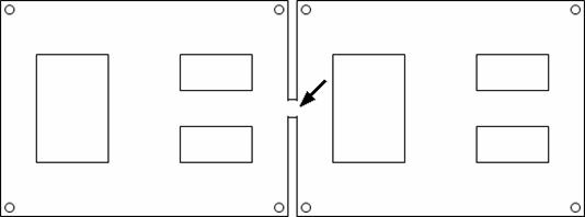
The Max. Bridge Size is the maximum distance between the part boundaries. If the distance exceeds the value, the system will chain cut the part.
The Max. Chain Length value determines whether parts are included in the range of the chain cut or are excluded from the chain cutting process. If you enable the option, and there are parts outside the specified distance value, the system will not chain the parts together. The system breaks the chain at the part and processes it separately. If you disable the option, the system will chain cut all the parts on the sheet, no matter how far apart.
|
This part is spaced farther away from the remaining parts. If it exceeds the Max Chain Length value, it will not be chain cut if there is a check mark in the check box. |
The options in the Skip Parts Information section allow you to skip parts in both the X and Y directions. You will find this feature useful to reduce the heat that is generated in one area of the sheet. There are two options: Distance To Skip and Skip Next Adjacent Part.
Notes:
1. The parts are sequenced according to the Sequence Direction and Starting Corner settings in the Sequence Info folder of the Machine Setup window.
2. When using cutout avoidance, the software only avoids cutouts within the part and will always call a head-up command between parts.
3. The software will always start each row from the same side.
If you want to skip parts using a specific distance, select this option and then type a value in the text box to the right. The system will skip any parts that fall within the specified distance value. The system interprets the distance value as a radius from the corner of the starting part. The following illustration depicts how the software interprets the Distance To Skip value:
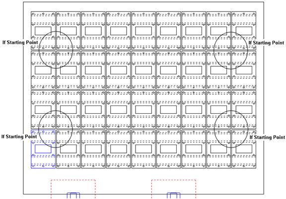
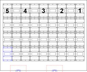
If the radius splits the center of a part, the software will skip the entire part. The software will sequence the parts in the selected direction, skipping the parts that are within the Distance To Skip value. Each time a part is cut, the virtual radius will move to the cut part to set the skip. When the sequence reaches the end of the row, the system will return to the start of the row and start sequencing the parts that were previously skipped. The following illustration displays the sequence order:
|
|
The
system will continue with this process until all of the parts in the row
have been cut. When the entire row has been cut, the software will proceed
to the next row. The processing will continue until the entire sheet has
been sequenced.
If you want the software to skip the next adjacent part in the sequence, select Skip Next Adjacent Part. The software ignores the distance value and simply examines the boundary for the adjacent part. It skips the adjacent part and attempts to detect a part beyond the adjacent part. If the system detects a part beyond the adjacent part, it sequences that part. The system will return to the start of the row and locate the first adjacent part that was skipped and sequence it. The software will continue to sequence the remaining adjacent parts that were skipped until the entire sheet has been sequenced.
Option |
Description |
OK / Cancel |
Click OK to keep any changes, or Cancel to close the window without saving.
|
Load |
Clicking the Load button displays the Open dialog box. If you want to change an existing tool inventory, use Open to load that tool inventory so you can make corrections. In addition to standard inv files, the user may choose to load from Tool Inventory files in .XLS or .CSV formats. From here it is also possible to create and edit .xls and .csv files. See Export below for more info on this.
|
Save |
To save changes made to material files, click the Save button. See Save for more info.
|
Save As
|
To save as an existing file that has been modified, click the Save As button. See Save As for more info.
|
| Export | Clicking Export opens the Save As window and allows the user to export files in .xls and .csv formats. See Exporting Files in XLS or CSV formats in the Material Files folder for more info on creating and editing .xls and .csv files.
|
To print the Material Type window with entries in the Material Type and Comments fields, click the Print button.
|
|
Apply All / Apply |
Click Apply All to apply all changes made in this window. Click Apply to apply only the most recent change. |