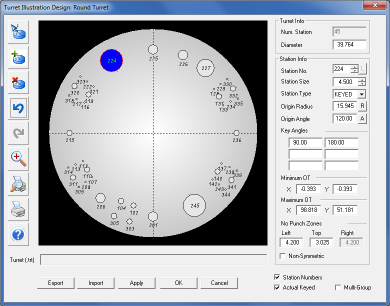
The Turret Illustration Design window allows you to create a turret illustration for your machine setup or import a turret illustration for modification. From the System Setting tab, select Turret Illustration to launch the Turret Illustration Design module.
See also Adding Tools to the Turret and Turret Window for more instructions.
Export |
To save a turret design, click the Export button in the Turret Illustration window. The Export Turret Station Information window will appear. Type a name for the illustration in the File name: text box. The system will store the turret information in the \TurretIllustration folder by default when you click the Save button. The turret illustration is linked to the machine (*.mac) file after you save it. When you load the machine file, the system will also load the associated turret illustration.
|
|
|
Import |
Click the Import button in the Turret Illustration window to open a turret design that you previously saved. The Import Turret Station Information window will appear. The system will list the turret information files stored in the \TurretIllustration folder by default. Select the desired file and then click Open to load the file. |
|
|
Add |
If you select Apply, the settings you have made are saved and you can continue making changes to the turret illustration. |
|
OK / Cancel |
If you select OK, the settings you have made are saved and the system will close the Turret Illustration window. |
|
|
If you click Cancel, the settings you have made are discarded and the system will close the Turret Illustration window.
|
|
Station Numbers |
When Station Numbers is checked, the station number for each station will appear directly below the station. For larger stations the number will appear at the center of the station. If the station number locations interfere with other stations the user has the option to relocate the station number. (See Station No. below.) Station Numbers also display when the Turret illustration is right-clicked; however, Station Numbers cannot be edited here. To edit Station Numbers, see Station No. below.
|
|
Actual Keyed |
This option functions as a toggle. If you place a check mark in the check box, the Key Angle markers that indicate the specified angles for the KEYED stations will shift relative to the actual origin of the machine. |
|
|
|
|
|
|
|
Multi-Group |
This option allows you to designate the selected station as a multi-tool station. (See Multiple Group Stations under Editing Stations.) |
|
Button |
Name |
Description |
|
Edit Stations |
Click the Edit Stations button to activate Edit mode when defining multi-tool stations. Select the station you want to define as a multi-tool station, select Multi-Group in the lower right-hand corner of the window and then click the Edit Stations button. Double-click the selected station to update the window. (See Multi-Group Stations under Editing Turret Stations.) |
|
Add New Stations |
Click the Add New Stations button to add a station to the turret. (See Editing Turret Stations.) |
|
Delete Selected Stations |
Click the Delete Select Stations button to remove the selected station from the turret. (See Editing Turret Stations.) |
|
Undo |
Click the Undo button to reverse the last command or action. |
|
Redo |
Click the Redo button to repeat the last command or action. |
|
Zoom In |
This control button allows you to toggle between Zoom In and Zoom Out mode. When you click the button while the magnifying glass has an addition sign, you can zoom in or magnify an area of the turret illustration.
|
|
Zoom Out |
This control button allows you to toggle between Zoom In and Zoom Out mode. Click the button until the magnifying glass has a subtraction sign. You can then zoom out or reduce the view of the selected area.
|
|
Print Preview |
Click the Print Preview button to view the turret illustration in the Print Preview window. Note: When printing the Turret layout, if Station Numbers is checked, the system will print the layout with station numbers.
|
|
Print Stations |
Click the Print Stations button to print the turret illustration using the default report template. Note: When printing the Turret layout, if Station Numbers is checked, the system will print the layout with station numbers.
|
|
Help |
Click the Help button to access the on-line help system. The help system will display the topics related to the Turret Illustration Design module. |
Option |
Description |
Note: In order to use these edit options, a station must first be selected. |
|
Turret Info |
Use the options in this section to specify the turret parameters. |
Num. Station |
The number of existing stations in the turret. The system will set the Origin Radius and Origin Angle to zero for the stations when you first open an existing machine or when you create a new turret. |
Diameter |
The actual diameter for the round turret. It is important that this value is accurate, as it will determine the scale of each tool station within the display. |
Station Info |
Use the options in this section to specify the parameters for each station within the turret. |
This is the Tool Station Number. You can type a station number or use the arrow buttons to specify the station number in increments of one. You must always specify the station number as a numerical value. The “L” (Location) button that is located next to Station No. allows the user to move the location of each station number (not the station itself). When the button is selected, the user can move into the turret display and the cursor will snap to the currently selected station number. The number will be attached to the cursor, and when the cursor is moved to the correct location and the left button is clicked, the number will be locked into the turret display. |
|
Station Size |
The size of the station. You can type the size or use the arrow buttons to specify the station size. The station graphic in the window will scale in size relative to the Diameter value of the turret. |
Station Type |
There are five types of stations: KEYED, NOTKEYED, AUTO (Auto-Index), MANUAL and CLAMP. Click the Type arrow to open the drop-down list and select the station type of your choice. |
Origin Radius |
This is the radius of the station relative to the center of the turret. (See Origin Radius.) |
Origin Angle |
This is the normal fixed origin of the station relative to the “0” or zero angle of the turret. (See Origin Angle.) |
Key Angles |
These fields will become available if you select KEYED from the Type drop-down list. You may specify up to six keyed angles for the station. |
Minimum OT X and Y |
The X and Y fields under Minimum allow you to specify the horizontal and vertical minimum overtravels for the selected station. The values indicate the furthest distance in the –X and –Y directions that the machine (or head) can travel. The numbers reference from the lower left corner of the sheet. Some machines can travel in these directions (the settings display as negative numbers), while other machines cannot (the settings display zero). |
Maximum OT X and Y |
The X and Y fields under Maximum allow you to specify the horizontal and vertical maximum overtravels for the selected station. These values indicate the furthest distance in the X and Y directions that the machine (or head) can travel away from its starting point. |
No Punch Zones |
Type the No Punch Zone for the left size of the clamps in the Left text box. If Non-symmetric is disabled, the setting is also used for the right side of the clamps. Type a No Punch Zone for the top of the clamps in the Top text box. If Non-Symmetric is enabled, type the No Punch Zone for the right side of the clamps in the Right text box. (See Creating and Editing Stations>No Punch Zones for more info.) |
|
|
|
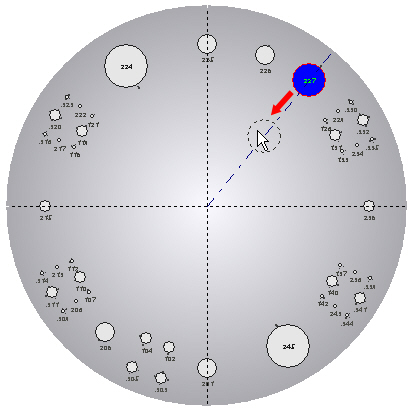
The Origin Radius is a measured from the center of the turret to the center of the tool station. The value you specify is relative to the center of the turret. You can type a value in the Origin Radius text box or move the station along the axis indicator to specify the origin radius of the station. (See Origin Angle.) |
|
Click the station you want to modify and then click the Origin Radius or [R] button. An origin radius axis indicator appears within the illustration. Drag the outline of the station along the axis indicator until the correct value appears in the text box. When you click the left mouse button, the station moves to the new position. You can also select the current value in the text box, type a value and press <Enter> to specify the new location. |
|
|
|
Moving the station to specify a new origin radius. |
|
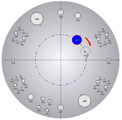
The Origin Angle is the normal fixed origin of the station relative to the zero angle of the turret. You can type a value in the Origin Angle text box or move the station along the angle indicator to specify the origin angle of the station. (See Origin Radius.) |
|
Click the station you want to modify and then click the Origin Angle or [A] button. An origin angle indicator appears within the illustration. Drag the outline of the station along the angle indicator until the correct value appears in the text box. When you click the left mouse button, the station moves to the new angle. You can also select the current value in the text box, type a value and press <Enter> to specify the new angle. |
|
|
|
Moving the station to specify a new origin angle. |
|
The Linear Position option only becomes available when you are creating a rack mount turret illustration. The Linear Position indicates the relative position of the station along the horizontal or X-axis from the end point of the tool rack. |
|
Click the station you want to modify and then click the Linear Position or [P] button. The station will follow the mouse pointer along the horizontal axis. Move the station along X-axis until the correct value appears in the text box. You can only move the station along the path between the adjacent stations. When you click the left mouse button, the station moves to the new position. You can also select the current value in the text box, type a value and press <Enter> to specify the new position. |
|
|
|
Adjusting the Linear Position of a station within the rack-mount turret. |