![]()
Select this option to manually place the part remover arms and suction cups on a part. See Use with Acies (and other combo) Machines below for specialized info.
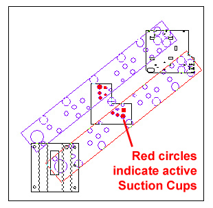
Click a part on the sheet to display the part remover arms directly over the selected part. (If necessary, double-click the part to zoom in.) If Auto Detect has been checked ON in the TK/PSR Settings window, the suction cups will activate when they are over the part. If Auto Detect is NOT checked on, then the user must activate suction cups by clicking on each cup over the part to be removed.
Note: If a PSR machine is loaded
Be Careful! Only suction cups directly over a part should be checked ON. If extra cups are checked ON, the part remover arm may also attempt to remove the sheet skeleton!
If Rotate Unloader is checked ON in the TK/PSR Settings window, then the arms may be rotated to any possible angle as shown below. Just place the cursor between the arms, left-click and drag the arms to rotate.
For the part remover arms to remove more than
one part
at a time, those parts must be placed into part
groups or kits
Left-click and drag with the cursor over the lower arm and both arms can be moved together. Left-click and drag with the cursor over the upper arm and it can be moved independently. To finalize the settings for the part remover arms, right-click once.
Arm position, angle, pickup positions in X/Y, Last Cut/Punch and arm distance in X/Y can be configured in the Properties dialog that displays when the arms are active.
Using this process the user can re-configure the arms separately for each part on the sheet. The user may also rely on default settings that can usually remove parts to the stacking table; however, in the event the system displays a warning that certain parts cannot be removed, try manual settings.
Note: Certain part remover arm behaviors are driver-dependent.
![]()
When the Amada Acies machine (or other Combo machine) is in use, the icon is named "Edit Arm, Final Cut." With this variation, the user must click-select individual parts, then drag the circle/cursor along the part perimeter, clicking again to place the final cut. At this point the part remover arms display and can be edited.
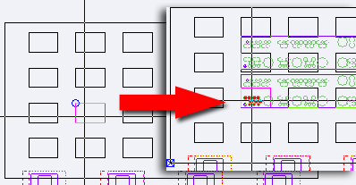
The image on the left shows the circle/cursor
When the final cut is placed, the removal arms
in the image on the right display for editing
Common Cutting with Multi-part Picker for Combo Machines
Multi-part picking for Common Cutting using Straight Edge Cut for Combination machines is now supported.
Select Straight Edge Cut in the Common Cutting window. Grid parts (do NOT group parts using Group options in the Sheet tab) and choose Set Spacing Equal to Beam Width for the grid. In Cut Sequence select Process All Grids in the Common Cutting submenu.
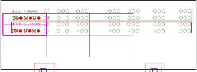
Go to the Modules tab and, using options in the Unloading Group submenu, Select two parts to enclose in a group (as in the image below). Click Edit Arm and assign the part remover arm to individual groups (see the instructions above on assigning the arm).
Go to the Cut Sequence tab and use Auto Sequence to sequence the sheet. Return to the Modules tab and use Manual or Auto options to unload the parts to the shuttle table.
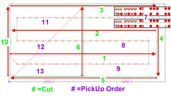
Continuous Pickup after one Final Call and Cut
Continuous cutting for Common Cutting using Straight Edge Cut for Combo machines is now supported.
With this option the system will cut internal rows 1 & 2 first and then cut the top (3), right & bottom (4 & 5) perimeters before cutting the center (6), which frees the right column (7, 8 & 9) of parts for removal with the Part Remover Arm. Finally, the left perimeter (10) is cut and the last parts can be removed (11, 12 & 13).