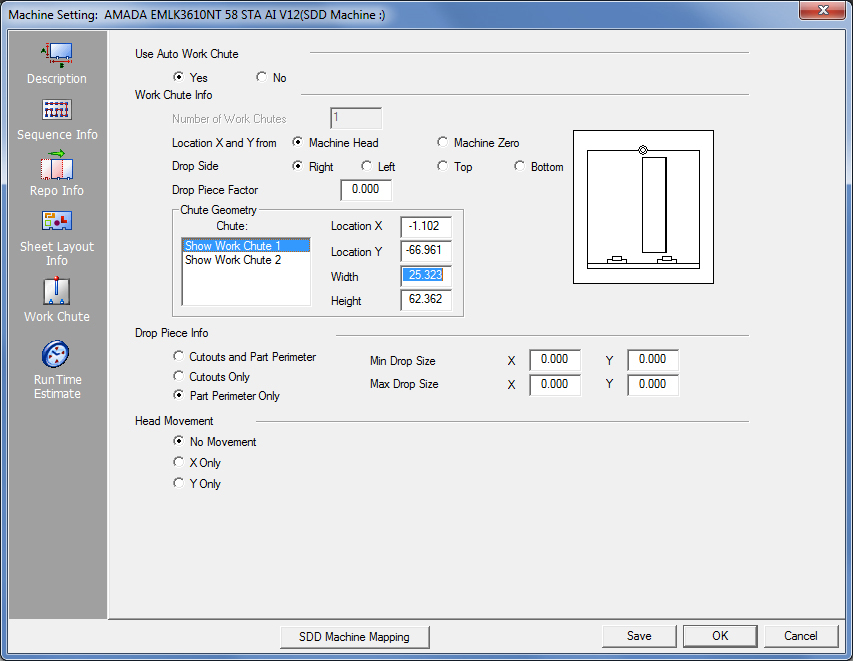
The Work Chute panel allows you to define and control machine work chutes or trap doors. Some options are available for both Auto Sequence and manual sequencing. As you type values and select options, the graphic to the right updates to reflect the changes.
Option |
Description |
|
Use Auto Work Chute |
Use the options in this section to activate the Auto Work Chute feature. Use Auto Work Chute is used only during auto-sequencing. The machine driver either enables or disables the chute function. |
|
Yes |
Select Yes if you want the system to use the work chute during an auto-sequence session. |
|
No |
Select No if you do not want the system to use the work chute during an auto-sequence session. |
|
|
Note: If patterns are grouped in grids or consist of line pattern groups, Use Auto Work Chute only analyzes the rectangular area of the group pattern to assign the work chute(s), not the actual size of the pattern(s) within the group. You will have to explode the patterns manually before the system can auto-sequence with the work chute(s). |
|
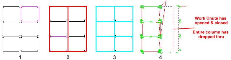
Work Chute Info Use the options in this section to define the work chute parameters. As you type values and select options, the table graphic updates to reflect the changes. Drop Parts Through Work Chute Column-by-Column When using a Combo machine, with gridded parts on a sheet, AP100US will drop parts through the work chute column-by-column as the laser cuts parts out in even columns.
Image 1 - Parts gridded with spacing between
parts equal to beam width. See the Common Cutting Module for more info on common cutting standards. The parts drop through the chute when the final vertical cut is completed. To enable this behavior Use Auto Work Chute must be checked ON and Auto Unloader in Sequence Info must be checked ON.
Parts in a Frame Kit on the sheet To reduce overall machine time, when AP100US detects that grouped parts in a frame kit are on the sheet, it will require the work chute to open/close once for all parts in that frame. At this point the entire frame will drop through the work chute. (For all other parts the chute will open/close one time per part.) Note: Using groups that are too large or contain large parts will cause this option to be ineffective. Part frame groups are generally used to enclose smaller parts. See Sheet Ribbon Tab>Group Parts for more info.
|
||
Number of Work Chutes |
This read-only field displays the number of work chutes or trap doors. The value is derived from the setting in the machine driver. |
|
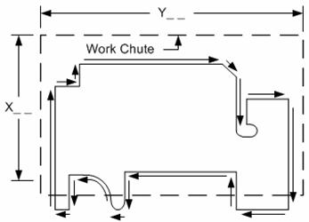
Location X and Y from |
Use the options in this section to specify the location of the work chutes relative to the machine head or machine zero. |
|
Machine Head |
Select this option if you want to use the machine head as the reference point when specifying the values for the work chutes. You should use this option if the machine head is in a stationary position relative to the work chute(s). |
|
Machine Zero |
Select this option if you want to use the machine zero as the reference point when specifying the values for the work chutes. You should use this option if the system repositions the machine head relative to the stationary work chute(s). |
|
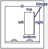
Drop Side |
Choose Right, Left, Top or Bottom to specify the drop side. The selected option allows the system to determine the position around the piece that is to be dropped. The selected side highlights the hinge position of the work chute in the table graphic.
Work Chute is shown
in the
|
|
Drop Piece Factor |
The value you type in the Drop Piece Factor text box allows the software to accommodate for odd perimeter cuts and internal cutouts. It is a multiple factor derived from the overall cut perimeter that is greater than the overall rectangular size of the work chute. The Drop Piece Factor compares the total overall part dimensions with that of the work chute. If you specify a value of zero, the software only examines the rectangular zone of the piece at that point. |
|
|
|
|
Chute Geometry Use the options in this section to define the parameters for each work chute or trap door. |
||
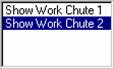
Chute List |
Each work chute that is supported by the system will appear in the Chute list. To modify the parameters for a specific work chute, click the name in the list to select it. You can then modify the values for the selected work chute. |
|
Location X |
Type a value for the X location of the work chute. The value references from the cutting head or the center of the punching tool, depending on your machine. |
|
Location Y |
Type a value for the Y location of the work chute. The value references from the cutting head or center of the punching tool. |
|
Width |
Type a width dimension for the work chute(s). |
|
Height |
Type a height dimension for the work chute(s). |
|
Drop Piece Info Use the options in this panel to specify the parameters for actual pieces that will drop down the work chute. |
||
Cutouts and |
Select this option if you want to drop the slugs along with the entire part. The option drops all items that fall within the minimum (Min. Drop Size X/Y) and maximum (Max. Drop Size X/Y) values. |
|
Cutouts Only |
Select this option if you want to drop only those pieces belonging to the internal geometry that fall within the minimum and maximum Drop Size values. |
|
Part Perimeter Only |
Select this option if you want to drop only those parts that fall within the minimum and maximum Drop Size limits. |
|
Min Drop Size |
Type the minimum X and Y limit values for the drop size. |
|
Max Drop Size |
Type the maximum X and Y limit values for the drop size. |
|
Head Movement Use the options in this panel to specify the movement of the machine head. |
||
No Movement |
Select this option if the machine head does not move in either the X-axis or Y-axis. The machine head is stationary; the clamps and machine table perform all the movement. |
|
X Only |
Select this option if the machine head moves in the X-axis, and the table moves in the Y-axis.
|
|
SDD Machine Mapping |
Clicking this button links the current machine in AP100US to a Machine registered in SDDJ. Data from the programs that have been stored into SDDJ can be linked to other products that link to SDDJ (such as AP100G CAM or Dr.ABE_Blank). Contact Sales Support to learn how to activate the SDDJ Server. Click for complete SDD information.
|
|
Save / OK / Cancel |
Clicking Save after making changes will save those changes as the default. Click OK to save changes only for this session (system reverts to default settings when program is closed). Click Cancel to cancel any changes and close the window. |
|