The Turret Illustration Design module supports three machine configurations: Round Turret, Rack Mounted Frame and Clamp Tools. This section will address the basic differences between these configurations and the methods you should employ to specify the station parameters for each turret type. (See Editing Turret Stations.)
The stations in a round turret configuration are aligned relative from the Origin Axis and Origin Angle. The Origin Axis is measured from the center point of the turret to the center point of the station. The Origin Angle is measured relative from the zero angle of the turret to the center point of the station. It is also important to specify the Diameter, as this affects the station sizes relative to the overall size of the turret. The system will update the value in the Num. Station field (Number of Stations) as stations are added or removed from the turret. |
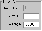
The stations in a rack-mounted frame are aligned along the center axis of the rack frame midpoint of the specified Width, but can be moved along the Linear position. Therefore, it is important to specify the correct Turret Width and Turret Length values for this machine type. The system will update the value in the Num. Station field (Number of Stations) as stations are added or removed from the turret. |
|
The stations in this configuration are represented as a series of clamps along the bottom edge of the sheet. The tools are removed from those stations that are designated as CLAMP-type stations. The display is dependant on the Table X and Table Y values, and the Clamp Ref Loc (Clamp Reference Location) and Clamp Interval values specified for the Clamp Settings. |
|
|