Editing Turret Stations

For round turrets and rack-mounted frame turrets, you can add or remove stations as needed using the click and drag method to draw them directly within the illustration area. For a clamp-tool configuration, you can edit each station individually, and specify the total number of stations, but you cannot draw stations.

Adding a Turret Station

Click the Add New Stations button to add a station to the turret illustration. The pointer becomes a small crosshair. Move the crosshair into the approximate position where you want to add the station. Click and hold the left mouse button. Drag in any direction until the correct or approximate value appears in the Size field in the Station Info section.


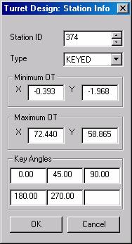
The Turret Design: Station Info window will appear when you release the mouse button. Type the appropriate values into the fields of the Turret Design: Station Info and then click OK. If necessary, correct the values in the Station Info section (Size, Type, Origin Radius, Origin Angle, Linear Position, etc.). See Single Tool Stations.

Deleting a Turret Station

Click the Delete Selected Stations button to remove a station from an illustration. Move into the illustration area and click the station you want to delete. The system will prompt you to confirm the action.


Click OK to delete the station or Cancel to exit without deleting the station.

Single Tool Stations

The Turret Design: Station Info window appears after you draw a new station in the illustration area. The software assigns the next sequential Station ID number automatically, but you can type a number in the Station ID text box, or use the arrow buttons to assign a Tool ID number to the station. You will want to define the station type by selecting the appropriate option from the Type list: KEYED, NOTKEYED, AUTO, MANUAL, SHEAR and LASERSTATION.

If necessary, specify the Minimum OT (Minimum Overtravel), Maximum OT (Maximum Overtravel) and Key Angles for the station. Click OK to save the machine parameters for the new station. See Multiple Group Stations.

Multiple Group Stations

Multi-group stations, also known as multi-tool stations, contain several substations within the tool assembly. To designate a station as a multi-group station, place a check mark in the Multi-Group check box. The station graphic will update to indicate that you can define substations within the station.


Single-Tool Station

Multiple Group Station


Double-click the multiple group station graphic to open the Multi-Group Station window. The Multi-Group Station window allows you to define the substations within the station using the same techniques previously described. The Turret Design: Station Info window will appear each time you draw a station within the illustration area. See Adding a Turret Station, Single Tool Stations and Multi-Group Station Window.

Multi-Group Station Window

The Multi-Group Station window shares many of the same functions as those found in the main Turret Illustration Design window for a round turret. You can add stations, delete stations and edit existing stations. You can adjust the values for the Station Number (Station No.), Size, Type, Origin Radius, Origin Angle, Key Angles, Minimum OT and Maximum OT for each substation as you would for a single-tool station. Click Apply and then OK when you have finished designing the multi-tool station. Click Cancel to exit without saving any changes.


Four substations within a Multi-Group station.

The Multi-Group station graphic will update and display the substations within the turret illustration area after you exit the Multi-Group Station window.