Display Part
List
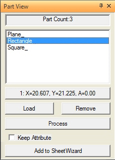
Clicking this
option opens the Part View panel shown here.
Part View panel
|
The options in the Part
View panel allow you to manage multiple part files. Usually,
only the last part loaded appears in the work area in Part
View. If you switch to Sheet View and load parts, the
system stacks the parts in the lower left corner of the sheet.
If you load a sheet layout consisting of several different parts,
only the active part appears in the work area when you switch
to Part View.
The Part View panel lists all the parts
currently loaded in the system. To display the window, select
the Display Part List icon on the Quick
Access Toolbar. If you click a file name in the Parts list,
the work area updates, displaying the selected part.
The Part View panel
also contains the Part Coordinate and Angle Indicator, the Keep
Attributes option, and Load, Remove and Process buttons. The following
paragraphs discuss these options in detail.
Part Coordinate and Angle Indicator
The Part Coordinate
and Angle Indicator button displays the sheet coordinates
and angle of the selected part. This feature is useful if you
have multiple instances of the same part on the sheet and want
to know the current location and angle of a specific part. Clicking
the button while SHEET View is active toggles through each
instance of the part on the sheet. |
Load
The
Load button in the Part View panel allows you to interactively
load *.prt, *.dxf, *.igs, *.dwg and *.iga files. When you click the Load
button, the Open File dialog box appears, listing the files stored
in the \Parts directory. The Open File dialog lists files having
the Parts (*.prt) extension by default, but you can click the Files
of type: arrow and select either DXF (*.dxf), IGES (*.igs),
DWG (*.dwg) or IGA (*.iga) to view the remaining file types
supported by AP100US.
Note:
The system automatically converts DXF, IGES, DWG and IGA files to the
*.prt format after you load them.
Batch Loading
You
can load multiple files by using the <Control> or <Shift>
keys and clicking the file names while the Open File dialog box
displays. This feature processes a batch of files.
Notes:
1. You
can use the batch loading technique only from the Part View panel.
2.
DXF, IGES, DWG or IGA files you select during the batch loading process
are converted into *.prt format. You can only load one file type
at a time.
3. If
Sheet View is active while you are batch-loading parts, the system
stacks the parts in the lower left corner.
4. If
you accidentally select a file that you do not want included in the batch,
hold the <Control> key and click the file again to deselect it.
To
batch load CAD files:
1. Make
sure Part View is active. The Part View panel appears.
2. Click
the Load button. The Open File dialog box appears.
3. Click
the Files of type: arrow and select the file type you want to load.
4. To
select multiple files, hold <Control>, and then click the individual
files. When you have selected the files you want to batch load, release
the <Control> key.
5. To
select a range of files, hold <Shift> and click the first and last
files of the group. When you have selected the group of files you want
to batch load, release the <Shift> key.
6. Click
Open to load the CAD files and then click Close to
exit the Open File dialog box.
Remove
The
Remove button in the Part View panel allows you to eliminate
a file from the list and sheet. When a part appears in the work area,
the system considers it the active part, and selects the file name in
the Parts list accordingly.
Note: The option only removes the
file name from the list and the part from the sheet. It does not delete
the CAD file from the hard drive.
To
remove a file, select the file name of the part you want to remove in
the Total Parts list. The work area displays the selected part. Click
the Remove button.
Process
The
Process button allows you to reassign the attributes if you make
any changes to the current part, machine file or material file. You can
process the current part or all the parts. See also Processing
Attributed Parts.
Notes:
1. If
Part View is active, only the active part in the work area is affected
when you click Process.
2. If Sheet View is
active, and you click Process, all the parts are affected.
3. If
any of the parts in the list have already been sequenced, the system prompts
you to confirm the processing.
4. The
Process button is disabled in Part View when the
Keep Attributes flag (Keep Attributes for Sheet Sequence) is enabled.
Keep Attributes
When
there is a check mark in the Keep Attributes check box for the selected
part, the software maintains any attributes and part sequencing after
the part is placed on the sheet. If you remove the check mark, the system
reassigns the attributes according to the criteria you specified in the
material file.
The
system displays a warning message if the part attributes vary from those
defined in the material file. You have the choice of maintaining the current
set of attributes assigned to the part or replacing the attributes with
those specified in the material file.
Saving Part Attributes
You
must save each file that appears in the Part View panel using the
<F10> key or by selecting the Save option from the File
menu. The system saves the attribute and machine driver information with
the part file.
If
you load an alternate machine, driver and material file, the software
attempts to apply the current attributes to the part when you reload it.
The system warns you if the part attributes do not match and that the
currently loaded attributes will be applied to the part.
Process Indicator
The
processing of complex parts can require some time. The Process Indicator
in the Status Bar displays the processing status.
Add
to Sheet Wizard
Press this button to have the program transfer all parts currently loaded
to the Sheet Wizard.
This action will remove the parts listed from the Part View panel.