![]()
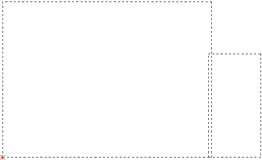
The Add Flange option is useful for developing a flat pattern from a drawing of a formed part. You will want to examine the part and define a view as the base flange. The base flange consists of equal bends that surround it, or an adjoining flange you want to use as a base. You draw the base flange first and then add the flanges to its perimeter. Note: To precisely position patterns try the Coordinates feature in the Draw menu.
Notes:Remember that your flange size must be exact. The system adds four new construction lines and recalculates the part size after attaching a flange. If you make a mistake, you can only remove the new flange by deleting the lines.
If you added the flange to the side that contained the reference point, the reference point appears in the new bottom left corner. When you complete the part layout, use the dimensioning options to check the new overall sizes. (See Dimensioning.)
You must define a step value that equals the setback or bend deduction before you can start adding the flanges. Move the crosshair into the work area, type the value of the setback, and press <S>.
Move the crosshair near the corner where you want to attach the flange. Click the right mouse button to snap to that corner. Next, press an <Arrow> key to move the pointer in the direction of the setback. The direction is dependent on the location of the flange you are adding and if it includes a bend allowance or setback.
You can begin the flange once you have the crosshair moving in the correct direction. Press <Enter> to begin the flange. When the system prompts you for the ending point, type the X and Y dimensions for the flange.
When the dimensions are correct, press <Enter> to secure the flange. The system redraws the flange and recalculates the part size. You can add more flanges as necessary when the part reappears.

Flange added to part