View Cutting Condition Table
The Cutting Condition Table is available only if there’s a JKA, JKAX, JKF, JKM, JKAM or JKMX link in the currently loaded machine. The read-only reference data is pulled from JKA, JKAX, JKF, JKM, JKAM or JKMX information.

Note: An option exists which allows the user to edit individual fields in the tables shown above for a special reason (such as for testing). The user must contact the Amada Call Center for assistance in enabling this feature. With this feature the user may only OK changes (takes effect only for the current session), but Saving is not allowed.
--CAUTION--
Settings
in this window CANNOT differ from those in the Controller.
For this reason this option is not available without permission and
assistance from the Amada Call Center.
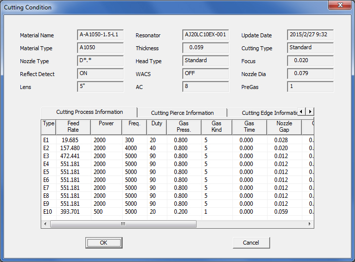
These read-only settings are for cutting machines. The system will detect when a driver is loaded, and decide if the machine is only for cutting, punching or a combo. If the driver only supports punching, then the entire Cutting Condition section will be disabled. |
|
Material Name |
Displays laser material name. This name is from the selected material type and material thickness from the JKA (or other JK...) file. |
Material Type |
The type of material used, such as CRS, Stainless or Aluminum. |
Nozzle Type |
Displays the type of the nozzle being used for processing. (Setting range: S*.*, D*.*W, S*.*E, D*.*E, D*.*) The characters “*.*” indicate the nozzle diameter. |
Reflect Detect |
Displays ON or OFF if the reflected light detection function is turned on or off. Note: The reflected light detection function must be ON when cutting aluminum. |
Lens |
Display the lens being used for processing. (Setting range: 5”, 7.5”, 10”, 3.75”, N/A) |
Resonator |
Shows the name of the oscillator installed on the machine. |
Thickness |
The Thickness of the material being used. |
Head Type |
Shows the type of laser head being used for processing. (Setting range: Standard, WACS, ECO) |
WACS |
Selects whether to turn on or off the WACS (Water Assisted Cutting System) function. This does not apply when the machine is not equipped with the WACS function. |
AC |
Active Cutting (also called “Adaptive Optics”) is a feature that helps to maintain the lens, by regulating lens temperature for example. AC is usually used for thick material such as aluminum. (Setting range: from 1 to 20. The setting depends on the material being cut.) |
Update Date |
Shows the date and time of the most recent update. |
Cutting Type |
Displays the cutting method. Types are - Standard: Oxygen cutting of mild steel (less than 6.0 mm in thickness) and stainless steel Thickness: Mild steel (6.0 mm or more in thickness) Clean: Clean Cut of stainless steel Aluminum: Aluminum Vinyl: Cutting of material with top surface covered with vinyl Acrylic: Cutting of acrylic
|
Focus |
Displays the fine adjustment amount of the focal point position. (Setting range: 0.0 to 99999.999) |
Nozzle Dia. |
Displays the nozzle diameter. |
List |
Click the List button to select a laser material name, and the Select Laser Material Name window displays. Single click on material name to highlight the entire row. Click Call (or double-click) to load the related cut condition into the AP100US program.
|
|
|
SDD Machine Mapping |
Clicking this button links the current machine in AP100US to a Machine registered in SDDJ. Data from the programs that have been stored into SDDJ can be linked to other products that link to SDDJ (such as AP100G CAM or Dr.ABE_Blank). Contact Sales Support to learn how to activate the SDDJ Server. Click for complete SDD information. |
Save / OK / Cancel |
Clicking Save after making changes will save those changes as the default. Click OK to save changes only for this session (system reverts to default settings when program is closed). Click Cancel to cancel any changes and close the window. |
Cutting Process Information tab

Type |
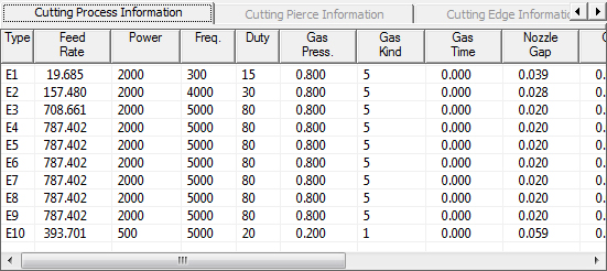
Displays the selected cutting condition type. Cutting conditions range from E1 through E10. If, for example, the cutting condition is E010, it implies scribing and not piercing. |
Feed Rate |
Feed Rate is the speed the laser cutting head moves at. This column shows the actual feed rate during program operation. |
Power |
Shows the actual power command value being used. (Setting range: 0 to 7000 W) |
Frequency |
Shows the pulse frequency command value, given in Hertz ranging from 5 to 2000. Note: A higher frequency gives more pulses (more frequent ON/OFF alternation) to the laser beam, and thereby, gives more output energy to the cutting material. |
Duty |
Displays the pulse duty command value to be used. The setting, given in percentage, ranges from 0 to 100. Note: “Duty” indicates the ON/OFF ratio of the laser beam. A higher duty number means a higher ratio of ON as compared to OFF; therefore, it gives more output energy. A Duty of 100 means continuous ON, which is CW (Continuous Wave) cutting. |
Gas Pressure |
Shows the pressure of the assist gas to be used. Settings range from 0.00 to 2.55 MPa. |
Gas Kind |
The type of assist gas to be used in the cut, such as oxygen, nitrogen or air. Settings range from 1 through 7, and are thus classified - 1 to 3: Oxygen, 4 to 7: Nitrogen, 5: Air, 6: EZ Cut. |
Gas Time |
Shows the assist gas change time. The machine waits for the preset time when it changes to the assist gas for cutting. |
Nozzle Gap |
Shows the nozzle gap. Nozzle Gap is the distance between the tip of the nozzle and the material surface. Generally, the nozzle gap should be about 1.5 mm. However, when performing high-pressure assist gas (stainless or aluminum) cutting, a much smaller nozzle gap (0.3 to 0.5 mm) is recommended. (Setting range: 0.000 to 9.999 mm) |
Offset |
Displays the cutter compensation value, which ranges from 0.00 to 9.99 mm (though it is usually 0.0079mm). |
Edge Data |
Displays the number for the edge process (0 or a value from 201 to 205). |
Approach Data |
Displays the number for the approach process (0 or a value from 201 to 205). The speed is given in inches per minute. |
Fine Data |
Shows which of the fine edge conditions is being used on the edge display. |
Pierce |
Displays under which of the piercing conditions on the PIERCE display to pierce the material. |
AC Offset |
Shows the compensation value for the Active Cutting unit during cutting. (Setting range: -5.00 to +5.00) |
Head Control |
Displays the method selected for moving the head after cutting. Setting range: Standard - Move the axis after raising the head. Medium - Raise and lower the head at a higher speed. Fast - Move the axis without raising the head. |
Cut Monitor |
Detects errors and attempts to auto-correct them. This column displays only when a JKAX file is in use. |
Cutting Pierce Information tab

Type |
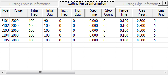
Displays the selected cutting condition type. Cutting conditions range from E1 through E10. If, for example, the cutting condition is E010, it implies scribing and not piercing. |
Power |
Shows the actual power command value being used. (Setting range: 0 to 7000 W) |
Initial Frequency |
Initial Frequency (always 5Hz) is when the oscillator has come on, but no cutting is taking place. Note: A higher frequency gives more pulses (more frequent ON/OFF alternation) to the laser beam, and thereby, gives more output energy to the cutting material. |
Initial Duty |
As with Initial Frequency, this is the moment when the laser is on, but there’s no cutting taking place. As soon as power increases, duty will go up. Note: “Duty” indicates the ON/OFF ratio of the laser beam. A higher duty number means a higher ratio of ON as compared to OFF; therefore, it gives more output energy. A Duty of 100 means continuous ON, which is CW (Continuous Wave) cutting. |
Increment Frequency |
Shows the increment pulse frequency command value, given in Hertz ranging from 5 to 2000. Note: A higher frequency gives more pulses (more frequent ON/OFF alternation) to the laser beam, and thereby, gives more output energy to the cutting material. |
Increment Duty |
Displays the increment pulse duty command value to be used. The setting, given in percentage, ranges from 0 to 100. Note: “Duty” indicates the ON/OFF ratio of the laser beam. A higher duty number means a higher ratio of ON as compared to OFF; therefore, it gives more output energy. A Duty of 100 means continuous ON, which is CW (Continuous Wave) cutting. |
Step Time |
Displays the step time during which the step piercing pulse frequency and duty increase. The range is from 0.00 to 9.99 sec. |
Step Count |
Displays the step time for high-speed piercing on a thick sheet. The range is from 0.00 to 9.99 sec. |
Pierce Time |
Displays the time required to complete the pierce. The range is from 0.00 to 9.99 sec. |
Gas Pressure |
Shows the pressure of the assist gas to be used. Settings range from 0.00 to 25.5 kgf/cm2. |
Gas Kind |
The type of assist gas to be used in the cut, such as oxygen, nitrogen or air. Settings range from 1 through 7, and are thus classified - 1 to 3: Oxygen, 4 to 7: Nitrogen, 5: Air, 6: EZ Cut. |
Gas Time |
Shows the assist gas change time. The machine waits for the preset time when it changes to the assist gas for cutting. |
Nozzle Gap |
Shows the nozzle gap. Nozzle Gap is the distance between the tip of the nozzle and the material surface. Generally, the nozzle gap should be about 1.5 mm. However, when performing high-pressure assist gas (stainless or aluminum) cutting, a much smaller nozzle gap (0.3 to 0.5 mm) is recommended. (Setting range: 0.000 to 9.999 mm) |
AC Offset |
Shows the compensation value for the AC unit during cutting. (Setting range: -5.00 to +5.00) |
Blow |
Material that is cut away during laser cutting either melts, burns, vaporizes, or is blown away by a jet of gas. Displays the blow pattern to be used to create this gas jet. |
After Pierce |
After Pierce actions can lift the head after a cut, or spray water to cool the sheet. (Setting range: OFF, ON) |
B Cut |
Sets the diameter of the small starting pierce hole. (Setting range: 0.0 to 9.9 mm) |
Pierce Type |
Sets the piercing method. Different types of pierce include: Standard Piercing (A0); Hi-speed piercing without internal process (A2); Power Piercing (A3); Quick Piercing (A6); Woodpecker piercing (A7); 2-step piercing (A8). |
Small Hole OFF |
This toggles the small hole ON/OFF. This column displays only when a JKAX file is in use. |
Pierce Monitor |
This toggle detects when the material is pierced so the cut can start. This column displays only when a JKAX file is in use. |
AO2 Pattern |
Adaptive Optic manipulates the beam, allowing a single lens to be used for all materials. This column displays only when a JKAX file is in use. |
Cutting Edge Information tab

Type |
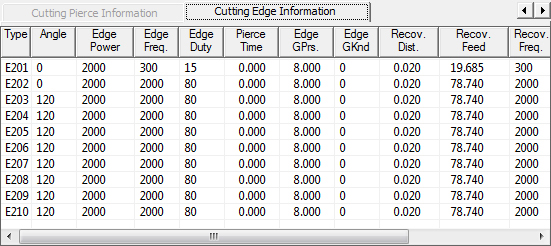
Displays the selected cutting condition type. Cutting conditions range from E1 through E10. If, for example, the cutting condition is E010, it implies scribing and not piercing. |
Angle |
Shows the intersecting angle of an edge portion at which the edge conditions (0 to 180) are switched to. |
Edge Power |
Displays the power to be used for processing the edge of the material. |
Edge Frequency |
Works in conjunction with Edge Power above for processing edges. Note: A higher frequency gives more pulses (more frequent ON/OFF alternation) to the laser beam, and thereby, gives more output energy to the cutting material. |
Edge Duty |
Edge Duty works in relationship to the Power and Frequency for processing edges. Note: “Duty” indicates the ON/OFF ratio of the laser beam. A higher duty number means a higher ratio of ON as compared to OFF; therefore, it gives more output energy. A Duty of 100 means continuous ON, which is CW (Continuous Wave) cutting. |
Pierce Time |
Shows the specified edge piercing time (ranging from 0.0 to 99.9 seconds). |
Edge GPrs. |
Shows the corner piercing assist gas pressure and return processing gas pressure. (Setting range: 0.00 to 2.55 MPa) |
Edge GKnd |
Shows the assist gas type. 0: Gas type and pressure effective as cutting conditions, 1 to 3: Oxygen, 4, 7: Nitrogen, 5: Air, 6: EZ Cut (Setting range: 0 to 7) |
Recovery Distance |
Displays the distance by which recovery from the edge is made under the current conditions. |
Recovery Feed |
Shows the return processing feed rate. (Setting range: 0 to 9999 mm/min) |
Recovery Frequency |
This figure depends on the oscillator specifications. |
Recovery Duty |
The Recovery Duty Cycle (the minimum to the maximum duty cycle given in %) depends on the oscillator specifications. |
Nozzle Gap |
Shows the nozzle gap. Nozzle Gap is the distance between the tip of the nozzle and the material surface. Generally, the nozzle gap should be about 1.5 mm. However, when performing high-pressure assist gas (stainless or aluminum) cutting, a much smaller nozzle gap (0.3 to 0.5 mm) is recommended. (Setting range: 0.000 to 9.999 mm) |
Edge Type
|
Enter a value to control edge type. This column displays only when a JKAX file is in use. |