Menus
The
menu bar along the top of the program window contains a set of menu
items. If you select a menu item, a list of associated command options
appears. Use the mouse to navigate the menus by pointing to select
the desired option.
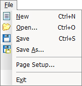
The File
menu consists of six options: New, Open…, Save,
Save As…, Page Setup… and
Exit.
New
Select
New from the File menu, or press <Control> + <N>
to create a new report template file. See Creating a New Report.
Open
Select
Open… from the File menu, or press <Control> +
<O> to open an existing report template file. See Opening
an Existing Report.
Save
Select
Save from the File menu, or press <Control> +
<S> to save a report template under its current file name. See
Saving a Report
Save
As
Select
Save As… from the File menu to save the currently open
report under a new file name. See Saving a Report.
Page
Setup
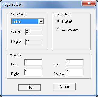
The
Page Setup… option on the File menu allows you to specify
the overall layout for the report. You can choose the paper size and
set the margins in the Print Setup dialog box.
Option |
Description |
Paper
Size |
Click
the Paper Size arrow button to select the paper size you normally
use for printing reports. |
Width |
This
is a static field. It displays the paper width. |
Height |
This
is a static field. It displays the paper height. |
Margins |
Type
values in each of the text boxes to specify the sizes of the
margins. |
Left |
Type
a value for the width of the left margin. |
Right |
Type
a value for the width of the right margin. |
Top |
Type
a value for the height of the top margin. |
Bottom |
Type
a value for the height of the bottom margin. |
Exit
Select
Exit from the File menu to quit the program. The system
will prompt you to save the current report.
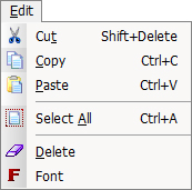
The Edit menu consists of six options:
Cut, Copy, Paste, Select All, Delete
and Font.
Cut
This option
will cut a selected object from the work area and place it on the
clipboard. To use this option, move the mouse point over the object
you want to cut and click it until the selection handles appear. Select
Cut from the Edit menu or press <Control> + <X>.
The selected object will disappear from the work area.
Copy
This option
will copy a selected object from the work area and place it on the
clipboard. To use this option, move the mouse pointer over the object
you want to copy and click it until the selection handles appear.
Select Copy from the Edit menu or press <Control>
+ <C>. The original object will remain visible in the work area.
Paste
This option
will paste an object that was cut or copied to the clipboard and restore
it to the work area. The cut or copied object will appear each time
that you use the Paste command.
Select
All
The Select
All option on the Edit menu will select all the objects
you have placed in the work area. Selection handles will appear on
all the objects to indicate the global selection.
Delete
The Delete
option on the Edit menu will erase a selected object. To use
this option, move the mouse pointer over the object you want to delete
and click it until the selection handles appear. Select Delete
from the Edit menu or press the <Delete> key. The object
will be deleted from the work area.Note: Any currently selected
object or objects in the work area are immediately deleted when you
use this command.
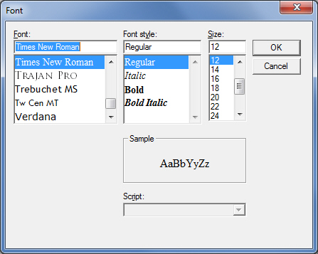
Font
The Font
option on the Edit menu will open the standard Font dialog
box. You can select a default font, font style and size for the text
and data field objects you place in the report.
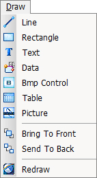
The Draw
menu consists of ten options: Line, Rectangle, Text,
Data, Bmp Control, Table, Picture, Bring
to Front, Send to Back and Redraw.
Line
|
The
Line option on the Draw menu allows you to create
a line object. See Line Properties. |

|
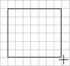
Drawing
a Line |
|
To
draw a line, select Line from the Draw menu
and move into the work area. Place the crosshair at the point
where you want to start the line. Click and hold the left
mouse button and then drag in any direction to draw the line.
Release the mouse button when you reach the end point location
for the line. |
|
|
|
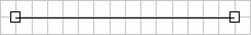
Selecting
a Line |
|
To
select a line, move the pointer onto the line and click it.
Selection handles appear at each end of the line. |

|
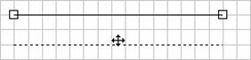
Moving
a Line |
|
To
move a line, move the pointer over the line until it becomes
move pointer. Click and hold the left mouse button. As you
start to drag, an outline of the object follows the pointer.
Drag the line to the desired location and then release the
left mouse button. |
|
|

|
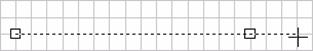
Sizing
a Line |
|
To
resize a line, click the line until the selection handles
appear. Move the pointer over a selection handle until it
becomes a resize pointer. Click and hold the left mouse button
and drag the end of the line you want to increase or decrease
in size. |
|
|
Deleting
a Line
To delete a line, click
the line until the selection handles appear. Click the Delete button
or press the <Delete> key.
Line
Properties
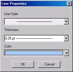
You
can modify the style, thickness or color of a line. Double-click the
line, or click the line until the selection handles appear and then
press <Enter>. Make the desired selections from the Line
Style, Thickness and Color drop-down lists and click
OK in the Line Properties window to apply the changes.
Rectangle
|
The
Rectangle option on the Draw menu allows you
to create square and rectangle objects. See Rectangle Properties. |
|
Drawing
a Rectangle |
|
To
draw a rectangle, select Rectangle from the Draw
menu and move into the work area. Place the crosshair at the
point where you want to start the corner of the box. Click
and hold the left mouse button and then drag diagonally in
any direction to draw the square or rectangle. Release the
mouse button when you reach the opposite corner location for
the square or rectangle. |
|
|
|
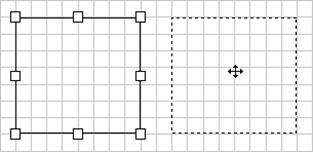
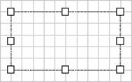
Selecting
a Rectangle |
|
To
select a rectangle or square, move the pointer inside the
rectangle or square and click the left mouse button. Selection
handles appear at each corner and at the midpoint of each
line of the square or rectangle. |
|
Moving
a Rectangle |
|
To
move a rectangle, move the pointer over the square or rectangle
until it becomes a move pointer. Click and hold the left mouse
button. As you start to drag, an outline of the object follows
the pointer. Drag the square or rectangle to the desired location
and then release the left mouse button. |
|
|
|
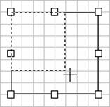
Sizing
a Rectangle |
|
To
resize a rectangle or square, move the pointer over a selection
handle until it becomes a resize pointer. Click and hold the
left mouse button and drag the corner or side until the object
increases or decreases to the desired size. |
|
|
|
Deleting
a Rectangle |
|
To
delete a square or rectangle, click the object until the selection
handles appear. Click the delete button or press the <Delete>
key. |
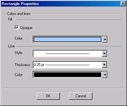
Rectangle
Properties
You can
modify the fill, color, style, line thickness and color of a square
or rectangle. Double-click the object, or click the object until the
selection handles appear and then press <Enter>. Make the desired
selections in the Rectangle Properties window and then click OK to
apply the changes.
Text
|
The
Text option on the Draw menu allows you to create
a label or text object. See Text Properties. |
|
Drawing
a Text Object |
|
To
draw a text object, select Text from the Draw
menu and move into the work area. Place the crosshair at the
point where you want to start the corner of the text box.
Click and hold the left mouse button and then drag diagonally
in any direction to draw the text box. Release the mouse button
when you reach the opposite corner location for the text box. |
|
|
|
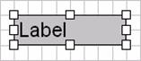
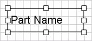
Selecting
a Text Object |
|
To
select a text object, move the pointer move the pointer inside
the label box and click the left mouse button. Selection handles
appear at each corner and at the midpoint of each line of
the text box. |
|
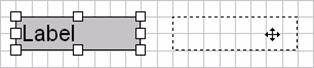
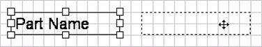
Moving
a Text Object |
|
To
move a label, move the pointer over the text box until it
becomes a move pointer. Click and hold the left mouse button.
As you start to drag, an outline of the object follows the
pointer. Drag the text box to the desired location and then
release the left mouse button. |
|
|
|
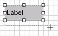
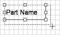
Sizing
a Text Object |
|
To
resize a label, click the label until the selection handles
appear. Move the pointer over a selection handle until it
becomes a resize pointer. Click and hold the left mouse button
and drag the corner or side until the object increases or
decreases to the desired size. |
|
|
|
Deleting
a Text Object |
|
To
delete a text object or label, click the object until the
selection handles appear. Click the Delete button or press
the <Delete> key. |
Text
Properties
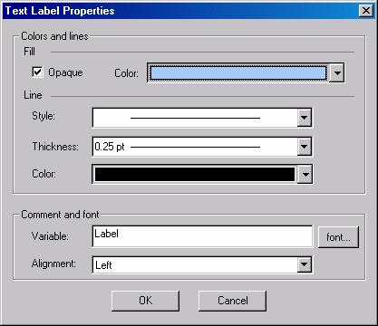
You can
modify the fill, line and comment properties for a text object or
label using the options in the Text Label Properties window. Double-click
the object, or click the object until the selection handles appear
and then press <Enter> to display the window. Make the desired
selections in the Text Label Properties window and then click OK to
apply the changes.
|
|
Option |
Description |
Fill |
|
Opaque |
Place
a check mark in the Opaque check box to fill the text
box will a solid color. Remove the check mark to make
the text box transparent. |
Color |
Select
a fill color from the drop-down list. |
Line |
|
Style |
Select
a line style from the drop-down list. |
Thickness |
Select
a line thickness from the drop-down list. |
Color |
Select
a line color from the color pallet. |
Comment and Font |
|
Variable |
The
default text of "Label" appears in the Variable
box. To type a new label, double-click "Label"
to select (highlight) it, and then type the desired
text. |
Alignment |
Select
an alignment for the text within the label from the
drop-down list: Left, Center or Right. |
|
Data
|
The
Data option on the Draw menu allows you to create
a data control or field object. See Data Control Properties
and Understanding Data Variables. |
|
Drawing
a Data Control |
|
To
draw a data object, select Data from the Draw
menu and move into the work area. Place the crosshair at the
point where you want to start the corner of the data box.
Click and hold the left mouse button and then drag diagonally
in any direction to draw the data box. Release the mouse button
when you reach the opposite corner location for the data box. |
|
|
|
Selecting
a Data Control |
|
To
select a data object, move the pointer inside the data box
and click the left mouse button. Selection handles appear
at each corner and at the midpoint of each line of the data
box. |
|
Moving
a Data Control |
|
To
move a data object, move the pointer over the data box until
it becomes a move pointer. Click and hold the left mouse button.
As you start to drag, an outline of the object follows the
pointer. Drag the data box to the desired location and then
release the left mouse button. |
|
|
|
Sizing
a Data Control |
|
To
resize a data control object, click the object until the selection
handles appear. Move the pointer over a selection handle until
it becomes a resize pointer. Click and hold the left mouse
button and drag the corner or side until the object increases
or decreases to the desired size. |
|
|
|
Deleting
a Data Control |
|
To
delete a data object, click the object until the selection
handles appear. Click the Delete button or press the <Delete>
key. |
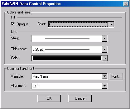
Data
Control Properties
|
You
can modify the fill, line and comment properties for a data
or field object using the options in the Data Control Properties
window. In addition, you can select a variable to display
the information contained in a specific database field. See
Understanding Data Variables |
|
Double-click
the object, or click the object until the selection handles
appear and then press <Enter> to display the window.
Make the desired selections in the Data Control Properties
window and then click OK to apply the changes. |
|
|
|
Option |
Description |
Fill |
|
Opaque |
Place
a check mark in the Opaque check box to fill the data
box will a solid color. Remove the check mark to make
the data box transparent. |
Color |
Select
a fill color from the drop-down list. |
Line |
|
Style |
Select
a line style from the drop-down list. |
Thickness |
Select
a line thickness from the drop-down list. |
Color |
Select
a line color from the color pallet. |
Comment and Font |
|
Variable |
The
field names that appear in the Variable drop-down
list are dependent on the report type. For example,
if you are creating a part report, then only those
fields associated with records in the part database
will appear in the list. See Understanding Data
Variables. |
Alignment |
Select
an alignment for the text within the data box from
the drop-down list: Left, Center or Right. |
|
Bmp
Control
|
The
Bmp Control option on the Draw menu allows you
to insert a bitmap or *.bmp files into the report. You can
use this feature to add a logo to your report. |
|
Drawing
a Bmp Control |
|
To
place a bitmap, select Bmp Control on the Draw
menu and move into the work area. Place the crosshair at the
point where you want to start the corner of the Bmp box. Click
and hold the left mouse button and then drag diagonally in
any direction to draw the Bmp box. Release the mouse button
when you reach the opposite corner location for the Bmp box. |
|
The
Open dialog box will appear and list the *.bmp files that
are stored in the default \TemplateReport folder. If necessary,
navigate to the desired folder that contains the *.bmp file
you want to insert. Click the file to select it and then click
Open. The bitmap object appears within the Bmp box. |
|
|
|
Selecting
a Bmp Control |
|
To
select a Bmp object, move the pointer inside the Bmp box and
click the left mouse button. Selection handles appear at each
corner and at the midpoint of each line of the Bmp box. |
|
Moving
a Bmp Control |
|
To
move a Bmp object, move the pointer over the Bmp box until
it becomes a move pointer. Click and hold the left mouse button.
An outline of the object follows the pointer as you begin
to drag. Drag the Bmp box to the desired location and then
release the left mouse button. |
|
|
|
Sizing
a Bmp Control |
|
To
resize a Bmp control object, click the object until the selection
handles appear. Move the pointer over the selection handle
until it becomes a resize pointer. Click and hold the left
mouse button and drag the corner or side until the object
increases or decreases to the desired size. |
|
|
|
Deleting
a Bmp Control |
|
To
delete a Bmp object, click the object until the selection
handles appear. Click the Delete button or press the <Delete>
key. |
Table
|
You
can insert a table into a report to present data in a columnar
format. There are two types of tables: a Bending Report Table
and a Turret Tool List Table. The data in the Bending Report
Table corresponds to the bend properties you have defined
for all the construction or bend lines in a part. The data
in the Turret Tool List Table corresponds to all the station
information you have defined in the turret setup. See Table
Properties. |
|
Drawing
a Table |
|
To
draw a table, select Table from the Draw menu
and move into the work area. Place the crosshair at the point
where you want to start the corner of the table. Click and
hold the left mouse button and then drag diagonally in any
direction to draw the table. Release the mouse button when
you reach the opposite corner location for the table. |
|
|
|
Selecting
a Table |
|
To
select a table object, move the pointer inside the table box
and click the left mouse button. Selection handles appear
at each corner and at the midpoint of each line of the table
box. |
|
Moving
a Table |
|
To
move a table object, move the pointer over the table box until
it becomes a move pointer. Click and hold the left mouse button.
An outline of the object follows the pointer as you begin
to drag. Drag the table box to the desired location and then
release the left mouse button. |
|
|
|
Sizing
a Table |
|
You
should modify the table properties before you attempt to resize
it. You will want to choose a table format and the data columns
you want to include in the columnar layout. See Table Properties. |
|
To
resize a table, click the object until the selection handles
appear. Move the pointer over the desired selection handle
until it becomes a resize pointer. Click and hold the left
mouse button and drag the corner or side until the object
increases or decreases to the desired size. |
|
|
|
Deleting
a Table |
|
To
delete a table object, click the object until the selection
handles appear. Click the Delete button or press the <Delete>
key. |
Table
Properties
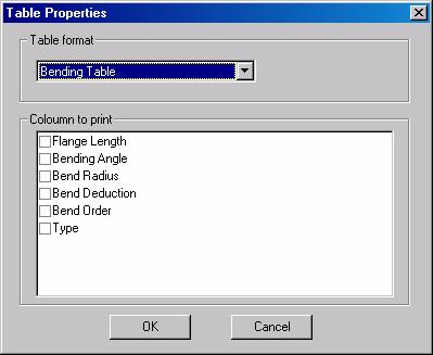
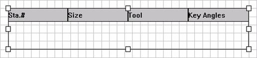
The system
will insert a default table into the report when you have finished
drawing it. The table will lack any labels along the top row. You
must therefore select the table type (format) and the columns that
you want to print. You can select the table and press <Enter>
or double-click the object to display the Table Properties window.
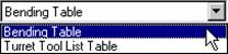
See Bending Table and Turret Tool List Table.
|
To
choose the actual format or type, select either Bending
Table or Turret Tool List Table from the drop-down
list: |
|
|
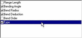
Bending
Table
|
If
you select Bending Table, the Column to Print
window will list the data fields that correspond to the bend
properties you have defined for all the construction or bend
lines in a part: |
|
|
|
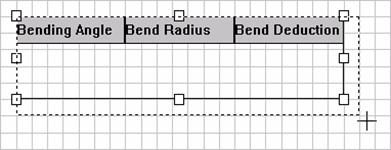
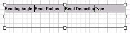
Place
a check mark in the appropriate check box to display a particular
column of information. If you remove the check mark, the column
will be omitted from the table. When you click OK, table will
update and the column names you selected in the window will
appear in the first row: |
|
|
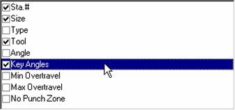
Turret
Tool List Table
|
If
you select Turret Tool List Table, the Column to
Print window will list the data fields that correspond
to all the station information you have defined in the turret
setup: |
|
|
|
Place
a check mark in the appropriate check box to display a particular
column of information. If you remove the check mark, the column
will be omitted from the table. When you click OK, table will
update and the column names you selected in the window will
appear in the first row: |
|
|
Picture
|
A
picture object will display a graphical representation of
the part, sheet or turret. For parts with bend properties
assigned to the construction or bend lines, the picture object
will display a three-dimensional image of the completed bend
process. See Picture Properties. |
|
Drawing
a Picture Object |
|
To
draw a picture object, select Picture from the Draw
menu and move into the work area. Please the crosshair at
the point where you want to start the corner of the picture
box. Click and hold the left mouse button and then drag diagonally
in any direction to draw the picture box. Release the mouse
button when you reach the opposite corner location for the
picture box. |
|
|
|
Selecting
a Picture Object |
|
To
select a picture object, move the pointer inside the picture
box and click the left mouse button. Selection handles appear
at each corner and at the midpoint of each line of the picture
box. |
|
Moving
a Picture Object |
|
To
move a picture object, move the pointer over the picture box
until it becomes a move pointer. Click and hold the left mouse
button. An outline of the object follows the pointer as you
start to drag. Drag the picture box to the desired location
and then release the left mouse button. |
|
|
|
Sizing
a Picture Object |
|
To
resize a picture object, click the object until the selection
handles appear. Move the pointer over a selection handle until
becomes a resize pointer. Click and hold the left mouse button
and drag the corner or side until the object increases or
decreases to the desired size. |
|
|
|
Deleting
a Picture Object |
|
To
delete a picture object, click the object until the selection
handles appear. Click the Delete button or press the <Delete>
key. |
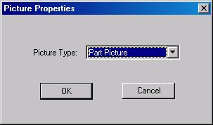
Picture
Properties
|
The
system will insert a default part picture into the report
when you have finished drawing it. You must therefore select
the picture type that you want to print. You can select the
picture object and press <Enter> or double-click the
object to display the Picture Properties window |
|
|
|
Click
the Picture Type: arrow button and select the desired
option from the drop-down list. Click OK to update
the picture object. |
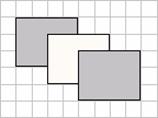
Bring
to Front
|
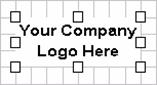
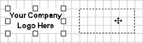
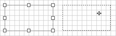
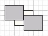
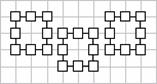
The
Bring to Front option will shift a selected object
to the foreground. The object will overlap any other objects
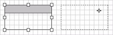
relative to it. In the example below, the Bring to Front option
was used on the center rectangle. The center rectangle now
overlaps the left and right rectangles. |
|
|
|
Before |
After |
|
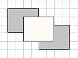
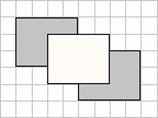
Send
to Back
|
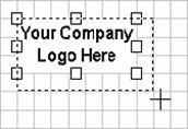
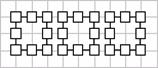
The
Send to Back option will shift a selected object to
the background. The object will be overlapped by any other
objects relative to it. In the example below, the Send to
Back option was used on the center rectangle. The left and
right rectangles now overlap the center rectangle. |
|
|
|
Before |
After |
|
Redraw
The Redraw
option will refresh the view in the work area.
|
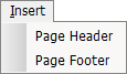
The
Insert menu has two options: Page Header and Page Footer.
A page header or footer can consist of page numbering, date
stamps and custom comments that clarify the contents of the
report. |
Page
Header
|
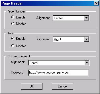
Select
Page Header from the Insert menu to define the
elements for the report header. See Header and Footer Options. |
|
|
Page
Footer
|
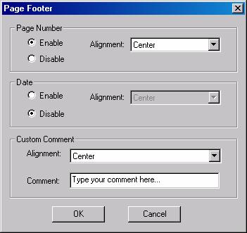
Select
Page Footer from the Insert menu to define the elements for
the page footer. See Header and Footer Options. |
|
|
Header
and Footer Options
|
The
Page Header and Page Footer windows share the same options.
The only difference is whether the elements are placed in
the header or footer section of the document. |
|
Option |
Description |
Page Number |
The
options in the Page Number group allow you to place
a page number code in the header or footer and to
determine the alignment. |
Enable |
Select
Enable to insert a page number in the header or footer. |
Disable |
Select
Disable to suppress the display of a page number in
the header or footer. |
Alignment |
Click
the arrow button and select an alignment for the page
number: Left, Center or Right. |
Date |
The
options in the Date group allow you to place a date
code in the header or footer and control the alignment. |
Enable |
Select
Enable to insert a date code in the header or footer.
The current date will appear in the header or footer. |
Disable |
Select
Disable to prevent the display of a date in the header
or footer. |
Alignment |
Click
the arrow button and select an alignment for the date:
Left, Center or Right. |
|
|
Custom Comment |
Use
the options in this section to insert any descriptive
text in the header or footer. |
Alignment |
Click
the arrow button and select an alignment for the comment:
Left, Center or Right. |
Comment |
Type
the text that you want to appear in the header or
footer in the Comment: text box. |
|
|
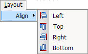
The
Left, Top, Right and Bottom options
on the Layout menu determine the alignment of selected
objects relative to each other. |
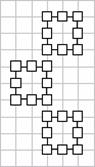
Left
|
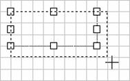
The
Left option on the Layout menu allows you to
align the left edges of all the selected objects. In the example
below, the two rectangle objects shift left relative to the
left edge of the left-most rectangle. |
|
|
|
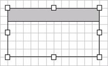
Before |
After |
|
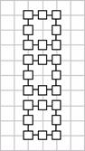
Top
|
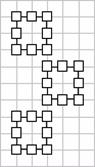
The
Top option on the Layout menu allows you to
align the top edges of all the selected objects to the top
edge of the top-most object. In the example below, the two
rectangle objects shift upwards relative to the top edge of
the top-most rectangle. |
|
|
|
Before |
After |
|
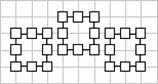
Right
|
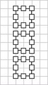
The
Right option on the Layout menu allows you to
align the right edges of all the selected objects. In the
example below, the two rectangle objects shift right relative
to the right edge of the right-most rectangle. |
|
|
|
Before |
After |
|
Bottom
|
The
Bottom option on the Layout menu allows you
to align the bottom edges of all the selected objects to the
bottom edge of the bottom-most object. In the example below,
the two rectangle objects shift downwards relative to the
bottom edge of the bottom-most rectangle. |
|
|
|
Before |
After |
|
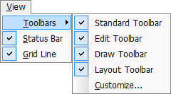
|
The
options on the View menu function as toggles. If an option
has a check mark, that element of the interface will appear.
If you remove the check mark, the interface element is hidden
from view.
The
Status Bar option on the View menu functions
as a toggle. A check mark next to the option will display
the status bar along the bottom of the application window.
If you remove the check mark, the status bar is hidden from
view.
The
Grid Line option on the View menu functions
as a toggle. A check mark next to the option will display
the grid lines in the work area. If you remove the check mark,
the grid lines are hidden from view.
The
options on the Toolbars submenu function as toggles. A check
mark next to an option will display that element of the interface.
If you remove the check mark, the element is hidden. |
|
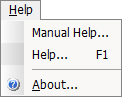
Select
Manual Help, Help F1 to open the manual or About
to display the copyright and version information. |
|
|