Chain and Bridge Cutting

The Chain/Bridge Cutting option allows you to use one continuous cut to process all the part profiles. The cutting system cuts each part in sequence and continues until the last part perimeter is cut. However, the system only cuts a portion of the perimeter and completes the cutting later in the sequence. See Chain Cut in Material Files for more information.
Topics covered on this page:
Chain/Bridge Cut Sequencing Options
Notes: Chain cutting processes both gridded and non-gridded parts. If processing a grid, it should be less than the travel zone.
Only the part boundaries are chain cut. Holes within the part perimeter are cut using a sequence that is similar to common cutting.
You cannot chain cut if parts contain parts. The gap between the parts should be greater than twice the beam width.
The chain cutting process overwrites microjoints and condition nodes on the part perimeters.
Patterns that you create in Sheet view are not included in the processing function of chain or common cutting.
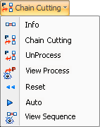
The Information, Chain Cut Starting Corner, Process, UnProcess and View Process options on the Chain/Bridge Cutting submenu prepare the parts for chain/bridge cutting.
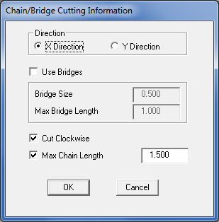
The Chain/Bridge Cutting Information window allows you to specify your chain/bridge cutting preferences. Select Info… from the Chain/Bridge Cutting submenu to display the window.

Direction
Use the options in this panel to choose
the direction of the chain cut.
X Direction
Select X Direction to specify chain/bridge
cutting along the horizontal axis.
Y Direction
Select Y Direction to specify chain/bridge
cutting along the vertical axis.
Use Bridges
Place a check mark in the check box
to enable the option, and then type values in the Bridge Size and Max
Bridge Length text boxes.
Bridge Size
Type a value in the text box to define
the size of the bridge(s).
Max Bridge Length
Type a value in the text box to define
the maximum distance between parts allowed for bridge cutting.
Cut Clockwise
Select this option to cut the part perimeters
in the clockwise. If you remove the check mark, the system cuts the part
perimeters counter-clockwise. See
Chain Cut Starting Corner.
Max
Chain Length
Type a value in the text box to specify
whether parts are included in the chain cut range.
The Direction (X Direction or Y Direction) and Cut Clockwise (enabled or disabled) options affect the actual starting corner when the system begins the chain cut. See the following illustrations: |
|
|
|
X Direction – Cut Clockwise enabled. |
X Direction – Cut Clockwise disabled. |
|
|
Y Direction – Cut Clockwise enabled. |
Y Direction – Cut Clockwise disabled. |
Use this option to process all the parts on the sheet for chain/bridge cutting. The system marks the shared paths for chain/bridge cutting. If you want to stop the processing, press <Escape>.
Use this option to reverse the processing of individual parts. Select UnProcess from the Chain/Bridge Cutting submenu. Move into the work area and click each part that you want to exclude from the chain/bridge cut. A part that you unprocess for chain/bridge cutting can be sequenced using the normal sequencing options.
Use the View Process option on the Chain/Bridge Cutting submenu to determine which parts are included in the chain/bridge cut.
You can use the sequencing options on the Chain/Bridge Cutting submenu to sequence the part boundaries.
If you need to clear the chain/bridge cut sequence, select Reset from the Chain/Bridge Cutting submenu. The system prompts you to confirm the action. Press <Y> to reset the sequence, and <N> to cancel.
Select Auto from the Chain/Bridge Cutting submenu to automatically sequence all parts on the sheet that were processed for chain/bridge cutting.
To see the chain/bridge cut sequence, select View Sequence from the Chain/Bridge Cutting submenu. This option only displays the chain/bridge cut sequence as the sheet redraws in the work area.