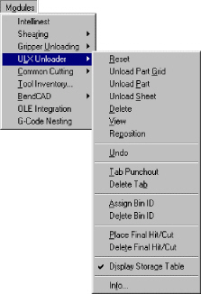
Amada ULX Unloader
What is the Amada ULX Unloader?
|
The Amada ULX Unloader module is an optional
software package that enhances the functionality of the CAD/CAM
System. The procedure outlined in this manual only addresses the
general features of ULX Unloader. Specific procedures vary from
one machine to the next. Please contact your Amada representative
for information specific to your machines. The ULX Unloader option
is located on the Modules menu. To access the options on the ULX
Unloader submenu, you must first open the Modules menu, and then
select the option (using the mouse or keyboard) to list the commands.
To ensure the options on the ULX Unloader submenu are active when
you begin your session, the following conditions must be in effect:
1. Your machine driver must support ULX
unloading functions.
Sheet
view must be active. You cannot use the gripper unloading
options if Part view is active. If the Info
option is active, but the remaining
options are disabled, you must use the Info
option first to specify the ULX
information. |
Quick Start Guide
The
Quick Start Guide summarizes the gripper unloading process. Review this
outline of the Gripper Unloading features. For commands or tasks you do
not fully understand, reference the appropriate section.
Start ULX Unloader
To prepare for ULX Unloader, launch the CAD/CAM
System. Select Sheet from the View
menu. Sheet view must be active before you
can use any of the options on the ULX Unloader submenu.
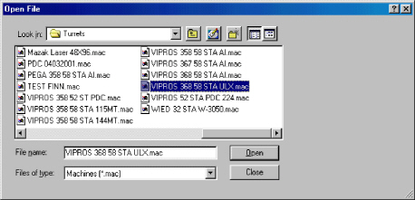
Load the Machine File

Select Open
from the File
menu, or click the Open File button in the
Standard toolbar. When the Open File dialog box appears, select
Machines (*.mac) from
the Files of type:
drop-down list. The system lists the machine files stored in the \Turrets
directory by default. If necessary, use the Look
in: drop-down list to navigate the
hierarchical folder structure. Scroll through the file list window and
click the name of the machine file. Click Open
to load the machine file. If necessary, edit
or load a material file. Click Close
to exit the Open File dialog box.
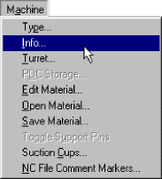
Load the Machine Driver
Select Info
from the Machine
menu to open
the Machine Setup window. Click the Driver File button.
The Open dialog box displays the machine drivers stored in the \Machine
directory by default. If necessary, use the Look
in: drop-
down
list to navigate the hierarchical folder structure. Scroll through the
file list window and click the name of the driver file. If necessary,
edit or load a material file. Close the Machine Setup window.
Specify the ULX Unloader Information

Open the Modules
menu. Select Info
from the ULX
Unloader submenu to open the ULX Unloader
window. Specify the Unloading Direction, Part Size Limitations, and Sheet
Unloading Location by either typing the values in the text boxes or by
selecting the appropriate option buttons. Click OK to save the ULX Unloader
information.
Create the ULX Unloader Sheet


Load
the parts on the sheet and grid them if necessary. Assign the tools to
the patterns. Place the final hits or cuts and assign the Bin IDs.
Sequence the ULX Functions
|
Use the
Reset,
Unload Part Grid,
Unload Part,
Unload Sheet,
Delete,
View and
Reposition options
on the ULX Unloader
submenu to remove the parts from the sheet.
You can also use the respective buttons on the toolbar to define
the
ULX unloading sequence.
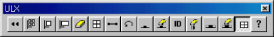 |
Save the ULX Sheet

Select Save
As from the File
menu, or click the Save As button in the Standard
toolbar to open the Save As dialog box. Select Sheets
(*.sht) from the Save
as type: drop-down list. Type an appropriate
name in the File name: text box. Click the Save
button to save the ULX sheet. Click the
Close button
to exit the dialog box.
Overview
The
basic procedure for using the Amada ULX Unloader includes:
Review or specify the Amada ULX Unloader
information, especially the sheet values for part limitations.
Create a part or parts and assign tools.
Define the sheet(s) and arrange the parts
on the sheet(s).
Place final hits or cuts. Technical support
representatives recommend using last
hits,
rather than
last cuts,
to minimize machine movement when freeing a part from the sheet.
Assign Bin IDs.
Sequencing the sheet.
Tab Punchout (optional).
Unload part grid or parts.
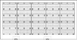
Amada ULX Sheet
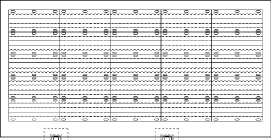
When working
with an Amada ULX sheet, use
the Zoom In option on the View menu to enlarge
the details. Use Zoom All on the View menu to
see both the sheet and the storage
area. |
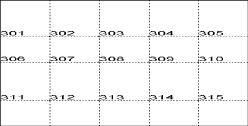
Amada ULX Storage
Area and Bin ID Numbers
|
Note: If you do not want to display the storage
area, remove the check mark from the Display
Storage Area option on the ULX Unloader
submenu. |
|
Preparation
Load the Machine File

A machine file contains the physical parameters
of a machine. You must load the correct machine file before you can define
a sheet having gripper functions. Machine files have the filename extension
of *.mac,
and are stored in the \Turrets directory by default.
To load the machine file:
Select Open
from the File
menu, or click the Open File button in
the Standard toolbar. The Open File dialog box appears.
Click the Files
of type: arrow and select
Machines (*.mac) from
the drop-down list.
If necessary, use the Look
in: list to navigate the hierarchical
folder structure.
Scroll
through the file list window and click the name of the machine file
you want to load.

- Click Open to
load the machine file, and then click Close
to exit the dialog box.
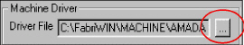
Load the Machine Driver
|
The next step involves checking the machine
driver, and if necessary, selecting the correct driver that supports
gripper-unloading functions. Your machine driver must support
gripper functions before you can use them. Please contact your
CAD/CAM System representative for more information on custom drivers.
Select Info
from the Machine
menu to open the Machine Setup
window. The Setup Values page
displays by default. Click
the Driver File  button in the Machine
Driver button in the Machine
Driver
section.
When the Open dialog box appears, the name of the current
driver displays in the File
name:
text box.
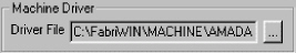
If the driver is correct, then click
the Close button to exit the Open dialog box.
To load an alternate driver, navigate through the file list
and click the name of the driver you want to load. Click the Open
button to load the driver. You
may be prompted to create or load a material file.
See the Material Files section
in Chapter 7: Machine Files of the CAD/CAM System manual for
more information. Click Save
in the Machine Setup window. |
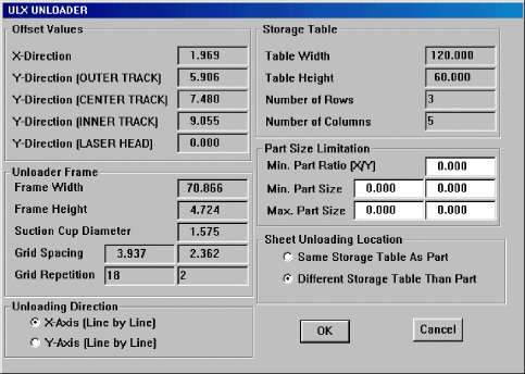
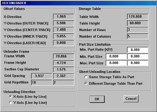
ULX Unloader Window

You
must specify the ULX Unloader information before you can use any of the
functions. If this information already exists in the machine driver, then
you only need to examine the values to ensure they are correct. If necessary,
you can view and edit the values for the part size limitations on the
sheet.
To
display the ULX Unloader window:
Make sure Sheet view is active. If necessary,
select Sheet from
the View menu.
Open the Modules
menu, and highlight (select) ULX Unloader to
open its submenu.
Select Info
from the ULX
Unloader submenu, or click the
Info button in the ULX toolbar. When the ULX Unloader window opens,
the contents of the X-Direction
text box in the Offset Values section
are selected by default.
Type
the values in the various text boxes. You can navigate the text box
fields within the window using a combination of the <Tab> and
<Shift> keys. Press <Tab> to move to the next field, or
<Shift> + <Tab> to select the contents of the previous
field.
When the information appears correct, click
the OK button
to save the changes and to exit the ULX Unloader window.
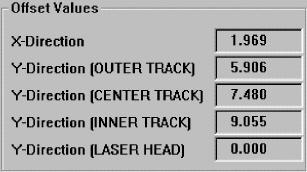
Offset Values
The
fields in the Offset Values section display information for the offset
from the punch head at the three track locations (or the laser head) as
measured in the X and Y directions to the center of the first pair of
suction cups.
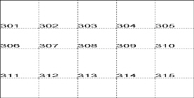
Offset Values Information
X-Direction The offset from the
turret station in the X direction.
Y-Direction
(Outer Track) The offset from outer track stations in the Y direction.
(Outer
track stations are 300 through 399.)
Y-Direction
(Center Track) The offset from the center track stations in the Y direction.
(Center
track stations are 200 through 299.)
Y-Direction
(Inner Track) The offset from the inner track stations in the Y direction.
(Inner
track stations are 100 through 199.)
Y-Direction
(Laser Head) For combination machines, the offset for the laser head in
the Y direction
(usually a negative value).
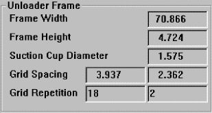
Unloader Frame
The
fields in the Unloader Frame section display information for the size
of the unloader frame that removes the parts.
Unloader Frame Information
Frame
Width The X measurement or width of the gripper frame.
Frame Height The Y measurement
or height of the gripper frame.
Suction
Cup Diameter The diameter of the suction cups.
Grid
Spacing The two fields following the label display the spacing of the
suction
cups in the X and Y directions respectively.
Grid
Repetition The two fields following the label display the number of suction
cups in
the X direction and Y direction respectively.
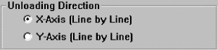
Unloading Direction
The
X-Axis (Line by Line) and Y-Axis (Line by Line) options in the Unloading
Direction section determine the direction the Amada ULX Unloader should
move when unloading grids of parts.
Unloading Direction Information
X-Axis
(Line by Line) This option instructs the system to move the unloader in
the X- axis before moving in the Y-Axis.
Y-Axis
(Line by Line) This option instructs the system to move the unloader in
the Y- axis
before moving in the X-Axis.
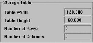
Storage Table
The
Storage Table section displays the parameters of the storage table that
holds the parts after unloading.
Storage
Table Information
Table Width The width or X dimension of the table.
Table
Height The height or Y dimension of the table.
Number
of Rows The number of rows available for storage on the table.
Number
of Columns The number of columns available for storage on the table.
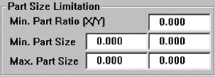
Part Size Limitation
The
Part Size Limitation information is critical.
Part Size Limitation Information
Min.
Part Ratio (X/Y) Type a ratio between the X dimension and Y dimension
of the part that the gripper can handle during
unloading. Divide the part's X by the Y, and then type the fraction that
results. A part having a ratio larger than this number can be unloaded.
This ratio ensures the weight of the part is supported when suction cups
cover the part's surface.
Min.
Part Size The minimum X and Y dimensions of the part the unloader can
handle.
Max.
Part Size The maximum X and Y dimensions of the part the unloader can
handle.
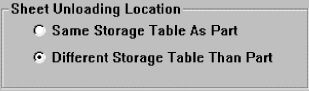
Sheet Unloading Location
This
section allows you to specify where the sheet should be unloaded.
Sheet Unloading Location Information
Same Storage Table As Part If
you select this option, the unloader stores the sheet
with the part.
Different
Storage Table Than Part If you select this option, the unloader stores
the sheet
in a different storage table than the part.
Save the Machine File
 To save
the changes you made to the machine file:
To save
the changes you made to the machine file:
Select Save
As from the File
menu, or click the Save As button in the
Standard toolbar. The Save As dialog box appears.
Select Machines
(*.mac) from the Save
as type: drop-down list.
Type an appropriate name in the File name: text
box.
Click the Save
button to save the machine file.
Click the Close
button to exit the dialog box.
Creating a Sheet with ULX Functions
Once
you have loaded the correct machine file and ULX driver, and specified
the correct values in the ULX Unloader window, you can add the actual
ULX functions to the sheet. This involves placing the final hits/cuts
and assigning the Bin IDs.
Note: Make
sure to check the gripper information before you begin. Use the
Info option
on the ULX Unloader submenu
to open the Unloading Gripper window.
Parts and Tool Assignments
To
begin the process, create the parts you want to arrange on the sheet and
assign tools to the patterns.

Notes:
See Chapter
8: Tool Assignment, in the CAD/CAM
System manual, for more information regarding tool assignments for
punching systems.
See Chapter
11: Cut Sequence, in the CAD/CAM
System manual, for information regarding tool assignments for cutting
and combination systems.
Layout the Sheet
Use the options on the Sheet menu or Sheet toolbar
to create the part layout. See Chapter
5: Sheet Layout, in the CAD/CAM System
manual, for more information.
Final Hits and
Cuts
Final
Hits are the last hits (or cuts) on the part. The system uses these hits
to break the part free from the sheet. You have two options: Place Final
Hit/Cut and Delete Final Hit/Cut. If you choose punched patterns, you
are defining the last hit. If you have a combination machine and select
cut patterns, you are defining the last cut.
Notes:
Before
placing final hits, you must assign tools to the last hit pattern
on each part.
When
choosing the last cut for a combination system, you cannot choose
a path having a start point or bridge microjoint. Technical support
recommends that you use last hits instead of last cuts.
A
sequenced single hit cannot be the final hit until you first reset
or remove the sequence.
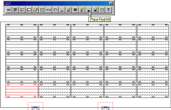
Place Final Hit/Cut
 To
place a final hit or cut:
To
place a final hit or cut:
Select Place
Final Hit/Cut from the ULX Unloader submenu,
or click the Place Final Hit button in the ULX toolbar.
Move
into the work area and click a pattern (a line, arc or tool hit placed
using Place Tool Hit) to assign the final tool hit or cut.
Slide
the mouse along the pattern to position the suction frame (the suction
frame is represented as a rectangle) and suction cups over the part.
Click
the left mouse button to select the position, and then use the left
mouse button to toggle the individual cups either on or off (active
cups appear in a solid color; inactive cups appear as concentric outlines).
When
you have activated the suction cups you want to use, click the right
mouse button.
Delete Final Hit/Cut

|
To remove a final
hit or cut: |
|
Select Delete
Final Hit/Cut from the
ULX Unloader submenu,
or click the Delete Final Hit button in the ULX toolbar. |
Bin IDs |
Move
into the work area and click each part from which you want
to remove the final hit. |
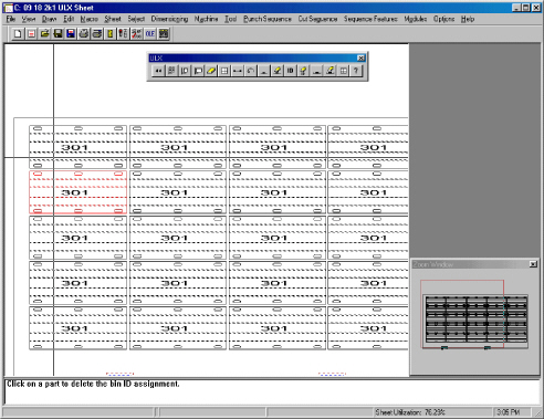
The
system uses Bin IDs as cross-references, assigning each part a particular
area on the storage table after it is broken out of the sheet. Your options
include assigning and deleting bin identification numbers.
Note: If
you do not assign bin identification numbers, the system prompts you for
the Bin IDs when you unload the parts or part grids. For part grids, you
can use this technique to unload the parts in different bins.
Assign Bin ID
 To
assign bin identification numbers:
To
assign bin identification numbers:
If necessary, display the storage table and
bin numbers. Make sure that Display
Storage Table on the ULX Unloader submenu
has a check mark, or click the Display Storage Table button in the
ULX toolbar.
Select Assign
Bin ID from the ULX
Unloader submenu, or click the
Assign Bin ID button in the ULX toolbar.
Move
the crosshair over a part or part grid that requires a bin identification
number and click the left mouse button. An outline of the part begins
to follow the crosshair.

Drag
the part into the storage area over the desired bin and click the
left mouse button. The part outline appears on the Bin ID.
The
Bin ID number assigned to each part displays within its part boundaries.
You can view these Bin ID numbers any time you select Delete Bin ID or
Assign Bin ID.
Delete Bin ID

To
remove bin identification numbers:
Make
sure Sheet view is active.
Select
Delete Bin ID from the ULX Unloader submenu, or click the Delete Bin
ID button in the ULX toolbar.
Move
into the work area. The Bin IDs appear on each part or part grid having
a bin identification assignment.
Click
each part or part grid from which you want to delete the Bin ID.
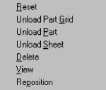
Sequencing the ULX Sheet
Once
you have placed the final hits/cuts and assigned bin IDs to the parts,
you are ready to sequence the ULX sheet. The Reset, Unload Part Grid,
Unload Part, Unload Sheet, Delete, View, Reposition, Undo, Tab Punchout
and Delete Tab options allow you to control the sequencing process.
Unload Part Grid

The
Unload Part Grid command allows you to unload an entire grid of parts.
If you have not yet punched bridge microjoints, this command sequences
them and the last hit before unloading all the parts in the selected grid.
If you want to control the sequencing order for the microjoint tabs, use
the Tab Punchout command.
Note: You
must assign the last hit before you can use this option.
To
unload a part grid:
Select Unload
Part Grid from the ULX Unloader submenu,
or click the Unload Part Grid button in the ULX toolbar.
Move
into the work area and click a part on the sheet belonging to the
grid.
If
the parts have Bin IDs, the system displays a series of driver-related
questions
in the message window and unloads the parts.
If the parts were not assigned Bin IDs, the system requests a bin
identification number for each part in the grid. Type the Bin ID number
and press <Enter>.
Unload Part

This command allows you to unload individual
parts. The bridge microjoints and last hit are sequenced before the system
unloads the part (See Unload Part
Grid). Use the Tab Punchout command
if you want to control the sequencing order for the microjoint tabs.
Note:
You must assign the last hit before you can use this option.
To
unload a part:
Select Unload
Part from the ULX
Unloader submenu, or click the
Unload Part button in the ULX toolbar.
Move
into the work area and click the part you want to unload.
If
the part has a Bin ID, the system displays a series of driver-related
questions in the message window and unloads the part. If the part
does not have a Bin ID, the system requests a bin identification number
for the part. Type the Bin ID number and press <Enter>.
Tab Punchout

|
Use this option
before unloading parts if you want more control over the sequencing
order for bridge microjoints. You must place bridge microjoints
on the part in Part view before you can use this option. Use Tab
Punchout after completing your sequencing and just before unloading
the part or part grid.
Note:
If you choose not to use Tab Punchout to sequence microjoints,
the Unload Part and Unload Part Grid options sequence the microjoints
using the same order as when they were originally added to the
part. The microjoints are sequenced just before the last hit is
punched.
To use the Tab Punchout option:
Select Tab
Punchout from the
ULX Unloader submenu,
or click the Tab Punchout button in the ULX toolbar. Move
the crosshair into the work area. Click
the part with microjoints that you want to sequence. The
pointer bounces between the bridge microjoints on the selected
part. Click each microjoint you want to punch using the left
mouse button in the order you want them punched. (The first
microjoint you click is punched first; the second is punched
second, and so on.) When
you finish sequencing the punch outs for tabs on the first
part, click the right mouse button so that you can continue
onto the next part. Click
the next part with microjoints that you want to sequence. Repeat
these steps for each part on the sheet for which you want
to control the sequencing of bridge microjoints. |
Delete
Tab |

|
The Delete Tab option removes the tab sequencing
you defined using the Tab Punchout command. To remove the tab
sequencing:
Select
Delete Tab from the ULX Unloader submenu, or click the Delete
Tab button in the ULX toolbar. Move
the crosshair into the work area. Click
the part with microjoints that you want to unsequence. The
pointer bounces between the sequenced bridge microjoints on
the selected part. Click each microjoint you want to unsequence
using the left mouse button. Click
the right mouse button when you want to unsequence microjoints
on a different part. Click
the next part with microjoints that you want to unsequence
and repeat these steps. |
Undo

|
Use the
Undo command
on the ULX Unloader
submenu, or click the Undo button
on the UXL toolbar, to reverse the last ULX sequencing command
you selected. |
Delete |

|
To erase an
unloading sequence for a part or part grid, select Delete from
the ULX Unloader
submenu, or click the Delete button
in the ULX toolbar. Move into the work area and click the part
or grid of parts. The sequence is removed from the part or part
grid. |
View |

|
To see the ULX
unloading sequence, select View
from the ULX
Unloader submenu, or click
the View Sequence button on the ULX toolbar.
Note:
Use the Viewing Speed command on the Options menu to control the
redraw rate of the sequence. |
Reposition |

|
Repositioning
allows you to move the work area to punch or unload parts that
are out of range. The repositioning function opens the clamps
and moves them so you can complete the remainder of the sheet.
You can also reposition in the reverse direction to return the
clamps so the sheet does not hang off the edge of the table.
To reposition the clamps during a ULX unloading sequence, select
Reposition from
the ULX Unloader
submenu, or click the Reposition button
on the ULX toolbar. The prompt instructs you to move into the
work area and set the reposition location. As you move the pointer
across the sheet, the reposition line appears and prompt asks
you to choose its location. The location of the reposition line
relative to the lower left corner of the sheet indicates the direction
and distance you want the clamps to move.
As you move closer to the left edge of the sheet, you will see
a rectangle following the pointer. This represents the machine
bed. The patterns that appear inside this rectangle are within
range. When the patterns you want to sequence with gripper functions
appear inside the rectangle, click the left mouse button. The
repositioning line locks onto the sheet, and two solid blocks
that represent the repositioning posts appear. The repositioning
posts follow the pointer around the work area and a prompt instructs
you to choose their placement. Make sure the posts do not fall
inside a cutout on the part. When you are satisfied with the location,
click the left mouse button. Use the other options to complete
the gripper sequencing after repositioning.
|
Reset |

|
The Reset option on the ULX Unloader submenu
allows you to clear any previous ULX unloading sequences. To clear
the unloading sequence, select Reset form the ULX Unloader submenu,
or click the Reset button in the ULX toolbar. The system prompts
you to confirm the action. Press <Y> for “Yes” to reset
the sequence, or <N> for “No” to cancel. |
Unload Sheet

|
When the sequencing
is complete, use the Unload Sheet command on the ULX Unloader
submenu, or click the Unload Sheet button on the ULX toolbar,
to unload the sheet. Note: You may want to review the Sheet Unloading
Location options in the ULX Unloader window to determine whether
the sheet unloads to the same storage area or to a different storage
area. See ULX Unloader Window
and Sheet Unloading Location. |
Display
Storage Table |

|
Display Storage Table is a toggle. It either
displays or hides the storage table when Sheet view is active.
If you enable the option, the storage table displays if you have
a ULX machine file loaded. To hide the display of the storage
table, remove the check mark. |
Saving the ULX Sheet

You
should save your sheet frequently to prevent data loss during power outages
or computer crashes. If you press the <F10> key while in Sheet view,
the system saves your sheet under its assigned name in its default folder.
Note: If
you have not yet named the sheet, pressing <F10> saves the sheet
with the default name of NEW SHEET.
To
save the sheet:
Make
sure you are in Sheet view. To save the sheet under a new name, select
Save As from the File menu, or click the Save As button in the Standard
toolbar. The Save As dialog box appears.
If necessary, select Sheets
(*.sht) from the Save
as type: list. Type a name in the
File name: text box. You need not add the filename extension; the
system automatically adds the *.sht
extension.
Click the Save
button to save the sheet. Click the
Close button
to exit the Save As dialog box.