Using SolidWorks™ with Special Tool Assignment and OLE
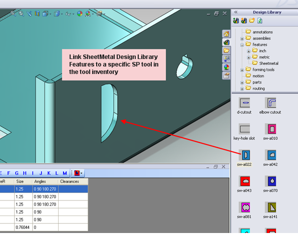
| Link Design Library items to a Specific Tool in the Inventory |
|
SolidWorks Tool Installation
Run (double-click or right-click-Open) SWTool.exe, which is located in the path of installation package SWTools folder.
![]()
Note: The SolidWorks Tool can be installed and registered automatically when installing products (such as AP100US). If the products are already installed, there is no need to install the SolidWorks Tool manually.
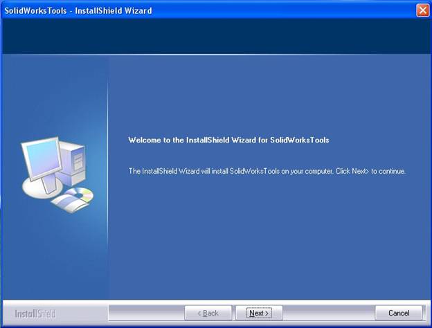
Welcome Screen
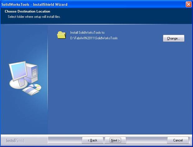
Choose Destination Location
This folder includes related SolidWorks Tools files and two sub folders (SPECTOOL and TOOLINV). The user should copy these files (*.spt and *.inv) to related folders in SolidWorks Tools.
Finish by Exiting the Wizard
After installation, SolidWorks Tools is registered automatically. If registration was successful, when SolidWorks is launched, the SolidWorks™ toolbar will show the Assign SP Tool, Export File, Mapping Table and Save Part to SDDJ tabs.
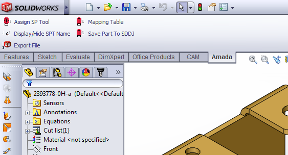
The SolidWorks toolbar now allows CAD/CAM tooling to be assigned by clicking on the Tool Assign menu item in the SolidWorks toolbar.
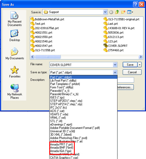
Export Special Tools to BMF/IGA/PRT format
Load Inventory into SolidWorks
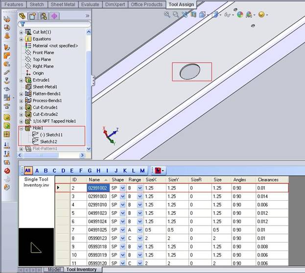
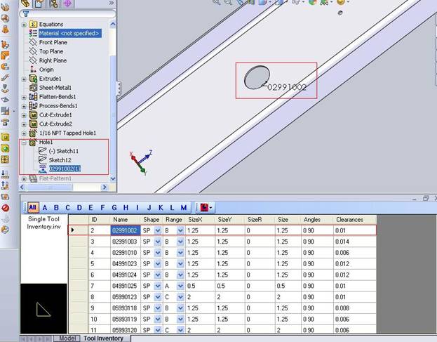
While a sheet metal part file in SolidWorks is open and the user selects Assign SP Tool from the toolbar menu, SolidWorks enters the “SP Tool Assignment” mode and a Tool Inventory dialog will be inserted at the bottom of the SolidWorks UI as in the image below. This Tool Inventory section will have the default Tool Inventory from the CAD/CAM program’s preference settings already loaded.
A different tool inventory file can be opened by opening Import Inventory.
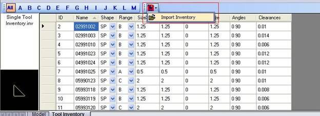
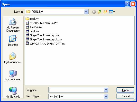
When the Import Inventory button is clicked, the Open File dialog will appear allowing the user to load a CAD/CAM program Tool Inventory file.
If a tool from the tool inventory is selected, that tool can be previewed in the Tool Preview pane to the left of the Tool List.
After selecting the CAD/CAM tool to be assigned from the Tool Inventory list, when the user selects the desired assignment feature of the SolidWorks part by left-clicking, the selected CAD/CAM tool will be assigned to that feature.
The SolidWorks Feature Tree will be updated to show the CAD/CAM Tool assignment instance created as a ‘child’ item of the assigned SolidWorks feature. The only SolidWorks features that can be assigned to the CAD/CAM SP tool are Forming items, which include Hole Wizard and Forming features.
When the user executes the OLE integration from the CAD/CAM program with SolidWorks, the system will read the process the attribute from the *.sdlprt file and auto-assign the SP tool(s).
When the CAD/CAM user performs the OLE Integration from SolidWorks, the system will auto-assign the SP tool to the forming features which the user linked in SolidWorks, assuming that the correct Tool Inventory is currently loaded inside the CAD/CAM program.
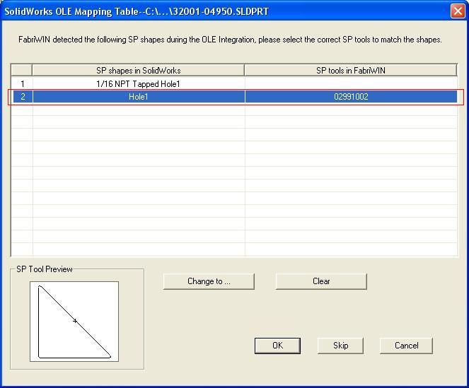
But if the user does not open the correct corresponding Tool Inventory in the CAD/CAM program, the system will not find the matching SP tool. This time, the OLE part will only have standard tooling assigned to it, or no tool will be assigned to that feature.
Note: If the user selects SP tools all features in SolidWorks parts, the system will not display the matching dialog, but will handle with SP tools data automatically.
A matching result in SolidWorks can be manually changed. First of all, the SP tool feature should be deleted manually in the SolidWorks part, then re-select a tool inventory and assign an SP tool to the forming feature. After saving the part, this setting will be updated.
Note: Inside the CAD/CAM program, the user must open the same Tool Inventory that was loaded into SolidWorks, which has the linked SP tool, and should be in the SPTOOL folder specified in the CAD/CAM settings. Otherwise, the system will not find the SP tool and the correct linked assignment will not occur.
Link Design Library items to a Specific Tool in the Inventory
Users may link "SheetMetal" Design Library Features to specific tools in the Tool Inventory. This alleviates the need to manually assign the SP tool, as it can be assigned automatically.
The CAD/CAM Tool will be automatically assigned as soon as the Sheet Metal Design Library Feature item is placed on the part.
The user can click Assign linked Tools to Design Library Features and all of the Design Library Features on the SolidWorks part that have a tool linked to them will have it assigned at that time.