Right Angle Shearing Manual
What is Right Angle Shearing?
|
The Right Angle Shearing module is an optional
software package that enhances the functionality of the CAD/CAM
System. If your machine driver supports right angle shearing on
right angle shearing machines, or a machine with a right angle
shear, then you will want to review the information presented
in this manual.
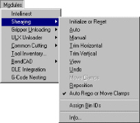
The Shearing option is located on the Modules menu. To access the
options on the Shearing submenu, you must first open the Modules
menu, and then select the option (using either the mouse or keyboard)
to list the commands.
To ensure the options on the Shearing submenu are active when you
begin your session, the following conditions must be in effect:
1. Your machine driver must support shearing
functions.
Sheet
view must be active. You cannot use the shearing options if
Part view is active. If the Info
option is active, but the remaining
options are disabled, you must first use the Info option
to specify the right angle shear information. |
Quick Start Guide
The Quick Start Guide summarizes the shearing
process. Review this outline of the Shearing features. For commands or
tasks you do not fully understand, reference the appropriate section.
Start Right
Angle Shearing
To
prepare for Right Angle Shearing, launch the CAD/CAM System. Select Sheet
from the View menu. Sheet view must be active before you can use any of
the options on the Shearing submenu.
Load the Machine File

Select Open
from the File
menu, or click the Open File button in the
Standard toolbar. When the Open File dialog box appears, select
Machines (*.mac) from
the Files of type:
drop-down list. The system lists the machine files stored in the \Turrets
directory by default. If necessary, use the Look
in: drop-down list to navigate the
hierarchical folder structure. Scroll through the file list window and
click the name of the machine file. Click Open
to load the machine file. If necessary, edit
or load a material file. Click Close
to exit the Open File dialog box.
Load the Machine Driver
|
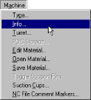
Select
Info from
the Machine menu
to open the Machine Setup window. Click the Driver File button.
The Open dialog box displays the machine drivers stored in the
\Machine directory by default. If necessary, use the Look in:
drop-down list to navigate the hierarchical folder structure.
Scroll through the file list window and click the name of the
driver file. If necessary, edit or load a material file. Close
the Machine Setup window.
|
Specify the Right Angle Shear Information

Open the Modules
menu. Select Info
from the Shearing
submenu to open the Right Angle Shear Information
window. Specify the Shearing Zones, Maximum Sizes, Offset From Punch Center,
Overcuts, Shearing Direction, Clamp Safety Zones, Clamp Positions and
Bin ID data.
Create the Right Angle Shearing Sheet
 Load the parts on the sheet and grid them if
necessary. Assign the tools to the patterns. Assign the Bin IDs.
Load the parts on the sheet and grid them if
necessary. Assign the tools to the patterns. Assign the Bin IDs.
Use the Shearing Options
Use
the options on the Shearing submenu to define the shearing sequence.
Save the Shearing Sheet
 Select Save
As from the File
menu, or click the Save As button in the Standard
toolbar to open the Save As dialog box. Select Sheets
(*.sht) from the Save
as type: drop-down list. Type an appropriate
name in the File name:
text box. Click the Save button to save the Shearing sheet. Click
Close to
exit the dialog box.
Select Save
As from the File
menu, or click the Save As button in the Standard
toolbar to open the Save As dialog box. Select Sheets
(*.sht) from the Save
as type: drop-down list. Type an appropriate
name in the File name:
text box. Click the Save button to save the Shearing sheet. Click
Close to
exit the dialog box.
Overview
The
basic procedure for using right angle shearing includes:
Review or specify the right angle shearing
information.
Review or specify the information for
the clamp safety zones.
Choose the shearing method, either automatic
or manual.
Choose the trimming method, either vertical
or horizontal.
Use either automatic repositioning or
manual repositioning.
Adjusting the clamp placement.
If necessary, using the Undo option to
reverse unwanted results.
Using the View command to see the shearing
sequence.
Preparation
To
prepare your system to use the shearing features:
Load your machine file, record the shearing
information, and bin information. You will want to save the machine
file to record the information for future production sheets.
Install your shearing machine driver as
outlined in the directions that accompanied it. Note: Only Version 5.x and later versions of the
CAD/CAM System support right angle shearing features.
Load the Machine File

A machine file contains the physical parameters
of a machine. You must load the correct machine file before you can define
a sheet having shearing functions. Machine files have the filename extension
of *.mac,
and are stored in the \Turrets directory by default.
To load the machine file:
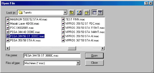
Select Open
from the File menu, or click the Open
File button in the Standard toolbar. The Open File dialog box appears.
Click the Files
of type: arrow and select
Machines (*.mac) from
the drop-down list.
If necessary, use the Look
in: list to navigate the hierarchical
folder structure.
Scroll
through the file list window and click the name of the machine file
you want
to load.

- Click Open to load
the machine file, and then click Close
to exit the dialog box.
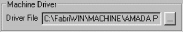
Load the Machine Driver
|
The next step involves checking the machine
driver, and if necessary, selecting the correct driver that supports
shearing functions. Your machine driver must support shearing.
Please contact your CAD/CAM System representative for more information
on custom drivers.
Select Info
from the Machine
menu to open the Machine Setup
window. The Setup Values page displays by default. Click
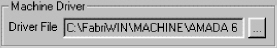
the Driver File  button in Machine
Driver section. When the Open
dialog box appears, the name of the current driver displays
in the File name: text box. button in Machine
Driver section. When the Open
dialog box appears, the name of the current driver displays
in the File name: text box.
If the driver is correct, then click
the Close button to exit the Open dialog box.
To load an alternate driver, navigate through the file list
and click the name of the driver you want to load. Click the Open
button to load the driver. You
may be prompted to create or load a material file.
See the Material Files section
in Chapter 7: Machine Files of the CAD/CAM System manual for
more information. Click
Save in the Machine Setup window. |
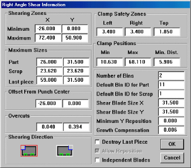
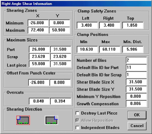
Right Angle Shear Information Window

You
must specify the right angle shear information before you can use any
of the options. If this information already exists in the machine driver,
then you only need to examine the values to ensure they are correct. If
necessary, you can view and edit the values using the Right Angle Shear
Information window.
To
display the Right Angle Shear Information window:
Make sure Sheet view is active. If necessary,
select Sheet from
the View menu.
Open the Modules
menu, and highlight (select) Shearing to
open its submenu.
Select Info
from the Shearing
submenu, or click the Info button in the
Shearing toolbar. When the Right Angle Shear Information window opens,
the contents of the X Minimum
text box in the Shearing Zones section
are selected by default.
Type
the values in the text boxes. You can navigate the text box fields
within the window using a combination of the <Tab> and <Shift>
keys. Press <Tab> to move to the next field, or <Shift>
+ <Tab> to select the contents of the previous field.
When the information appears correct, click
the OK button
to save the changes and to exit the Right Angle Shear Information
window.
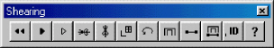
Shearing
Zones
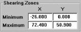 |
The shearing zone
is the area that your machine driver can shear. The text boxes
in this section allow you to specify the minimum and maximum X
and Y values for the shearing zone. The CAD/CAM System measures
these values from the lower left sheet corner. |
Shearing
Zones Values |
Minimum
(X and Y) |
These
fields allow you to specify the X and Y values for the minimum
shearing boundary. Type the value that represents the furthest
left position for shearing in the X text box, and the value representing
the lowest
position available for shearing in the Y text box. |
Maximum
(X and Y) |
These
fields allow you to specify the X and Y values for the maximum
shearing boundary. Type the value that represents the furthest
right position available for shearing in the X text box, and the
value representing the highest position for shearing in the Y
text box. |
Maximum
Sizes
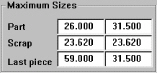
|
This section allows
you to specify the maximum sizes for parts,
remaining scraps and the last piece. |
Maximum
Sizes Values |
|
Part
(X and Y) |
Type
the maximum size for the largest part your machine can shear in
the X and Y fields following the label. |
|
Scrap
(X and Y) |
Type
the maximum size for the remaining scrap in the X and Y fields
following the label. |
|
Last
Piece (X and Y) |
Type
the maximum size for the last piece in the X and Y fields following
the label. |
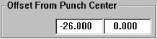
Offset
From Punch Center |
|
Type the X and Y
coordinates for the shear blade's offset from the punch center
in these text boxes. The distance is measured from the punch head
to the shear blade. (The punch head is considered “0, 0”.) You
must consult your machine's user guide or manual for this information. |
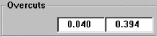
Overcuts |
|
The overcut is the
amount you want the blade to overlap hits when multiple hits are
required to remove the material. (This is similar to “nibbling”
in punching.) You must consult your machine's user guide or manual
for this information. |
Shearing
Direction
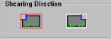 |
The options in this
section allow you to specify whether shearing should proceed from
left to right or right to left.
 to
shear from left to right. to
shear from left to right. |
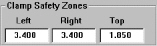
Clamp
Safety Zones
 |
 to
shear from right to left. to
shear from right to left.
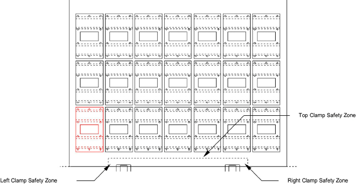
You use this
section to specify the safety zone required to the left of left-hand
clamp, to the right of the right-hand clamp and above the tops
of the clamps. Note: The shear cannot cut between clamps. It
can only shear to the right or left side of the clamps. The system
moves the clamps
as needed when you use automatic shearing. |
Clamp Safety Zones
Values |
Left
Right
Top |
Type the amount of space required as a safety
zone on the left side of the far left clamp.
Type the amount of space required as a safety
zone on the right side of the far right clamp.
Type the amount of space required above
the clamps. |
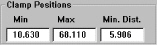
Clamp Positions
|
Use these settings
to specify the positions for clamps during right
angle shearing. |
Clamp Positions
Values |
Min |
Type the minimum
clamp position (as measured from the bottom left corner of the
sheet). |
Max |
Type the maximum
clamp position (as measured from the bottom left corner of the
sheet). |
Min. Dist. |
Type the minimum
distance between the clamps. |
Bin
Information |
|
Bins
represent the destinations of the parts after shearing.
Notes:
You
cannot assign parts to bins until you specify the number of
bins. If
you specify a value of zero in the Number of Bins text box,
you cannot use the Assign Bin IDs option. |
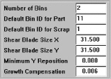
Bin Information |
Number of Bins |
Type the number of bins used for shearing. |
Default Bin ID for
Part |
Type the bin number you want to use for
parts that are not assigned to any other bin. |
Default Bin ID for
Scrap |
Type the bin number for the bin you want
to use for scrap. |
Blade Size |
The Shear Blade Size X and Shear Blade Size
Y text boxes contain the X and Y dimensions for the size of your
machine's shearing blade. You must consult your machine's user
guide or manual to obtain these values. |
Shear Blade Size
X |
The X dimension of the machine's shearing
blade. The orientation is dependent on the sheet as it
appears within the program window. The X dimension is the measurement
from left to right. |
Shear Blade Size
Y |
The Y dimension of the machine's shearing
blade. The orientation is dependent on the sheet as it
appears within the program window. The Y dimension is the measurement
from bottom to top. |
Minimum Y Reposition |
This field contains the value for the lowest
position that can be sheared when repositioning is active. |
Growth Compensation |
The value you enter in this field allows
you to compensate for the amount the shear stretches the
metal. You must rely on your own experience with the materials
and machines to arrive at the correct value. Some shops use 0.005”
as a baseline and adjust the value as needed for various materials
and machines. You must experiment with this setting to determine
how it affects the other machine settings. Grids are often affected
by this setting. |
13 |
Destroy Last Piece

|
For auto-shearing, this option indicates
whether the last piece of scrap should be sheared down to a manageable
size. The option ensures that the last piece is smaller than the
maximum scrap size. |
Allow Reposition |
To destroy the last piece, make sure a check
mark is in the check box. If you want the last piece to remain
in whatever size naturally occurs, remove the check mark from
the check box. |

|
This option
indicates whether your machine is capable of repositioning the
sheet. If a check mark appears in the check box, your machine
allows repositioning. If the option is disabled, then your machine
does not allow repositioning.
Note:
The system examines the machine driver to determine whether repositioning
is allowed. However, to actually use repositioning, you must place
a check mark in the All Reposition check box. You must also select
the Auto Repo or Move Clamps option on the Shearing menu until
a check mark appears next to the option. |
Independent
Blades |

|
This option indicates whether the machine's
blades can function independently. The Salvagnini is an example
of this type of machine. If the machine's blades function independently,
make sure to place a check mark in the check box. If the machine's
blades work simultaneously, remove the check mark from the check
box. |
Bin IDs
|
Bins hold your
parts. You must specify the number of bins your machine uses and
an identification number for each bin. You must then assign a
part or parts to a particular bin. You use the Assign Bin ID option
for this purpose. Note: Before you attempt to assign the parts
to the bins, make sure to complete your bin information setup.
Select Info from
the Shearing submenu and enter a value in the
Number of Bins text box. You will also want to enter the
setup values for Default Bin
ID for Part and
Default Bin ID for Scrap. |
Assign Bin IDs

|
To
begin the process, select Assign
Bin IDs from the Shearing submenu,
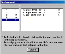
or click the Assign Bin IDs button in the Shearing toolbar. The
Bin Assignment window is split into bin number and part list panes.
The bin numbers available for your machine appear in the pane
on the left; the parts are listed in the pane on the right.
See Bin Number and Bin ID. See
also Part Name and Bin ID. |
Bin Number and Bin
ID |

|
To assign an ID number for each bin, double-click
any line in the left pane of the Bin Assignment window. The Bin#
window appears in the lower left corner of the Bin Assignment
window. Type a code number in this window and press <Enter>.
Repeat this procedure for each bin. |
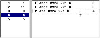
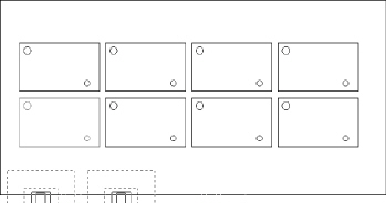
Part Name and Bin ID
The
next step involves assigning the parts to the bins. You want to click
a bin number in the left pane, and then click each part name you want
to assign to that bin. The following illustration indicates that the first
two parts are assigned to Bin# 3, while the third part is assigned to
Bin# 4.
To assign parts to a different bin, click the
next bin
number in the left pane, and then click the name of the part in the right
pane.
 When
you have completed your bin assignments, click Close
to exit the Bin Assignment window.
When
you have completed your bin assignments, click Close
to exit the Bin Assignment window.
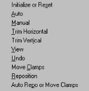
Shearing Options
You
have the choice of using either automatic or manual shearing. If time
is at a premium, then you may want the system to automatically shear the
sheet. If control over the shearing process takes priority, then try manual
shearing.
Automatic Shearing
If you choose to use automatic shearing, the
software determines how to shear the sheet. You can also choose to have
the system automatically reposition and move the clamps as needed, or
you can manually reposition the sheet. See
Using Automatic Repositioning and Using Manual Repositioning.
To
use automatic shearing:
Arrange
the parts on the sheet, and define the tool assignments and sequencing.
Select
Initialize or Reset from
the Shearing submenu,
or click the Initialize or Reset Shearing button in the Shearing
toolbar. The system prompts you to confirm. Press <Y> to reset
the shearing sequence or <N> to cancel.

|

|
Using Automatic
Repositioning |

|
Using Manual
Repositioning |

|
Manual Shearing
Manual shearing allows greater control the
shearing process. The overall procedure involves initializing the
sheet for shearing, choosing a trimming option, or manually shearing
the parts from the sheet.
Initialize or
Reset Shearing
 You must first initialize the sheet before performing
any manual shearing. If necessary, select Initialize
or Reset from the Shearing submenu,
or click the Initialize or Reset Shearing button in the Shearing toolbar.
You must first initialize the sheet before performing
any manual shearing. If necessary, select Initialize
or Reset from the Shearing submenu,
or click the Initialize or Reset Shearing button in the Shearing toolbar.
The system prompts you to confirm. Press
<Y> to reset the shearing sequence. Press <N> to cancel.
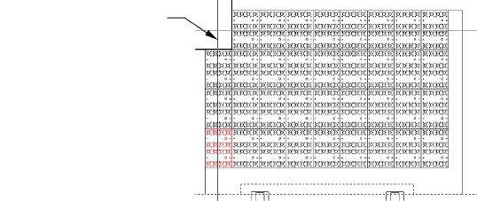
Trimming the Sheet
You must trim any material surrounding the
parts from the sheet before you can manually shear individual parts.
The Trim Horizontal and Trim Vertical options are used for this purpose.
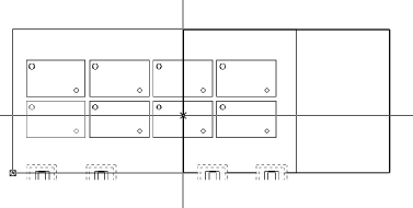
Trim Horizontal

To trim the sheet
horizontally, select Trim Horizontal
from the Shearing
submenu, or click the Trim Horizontal
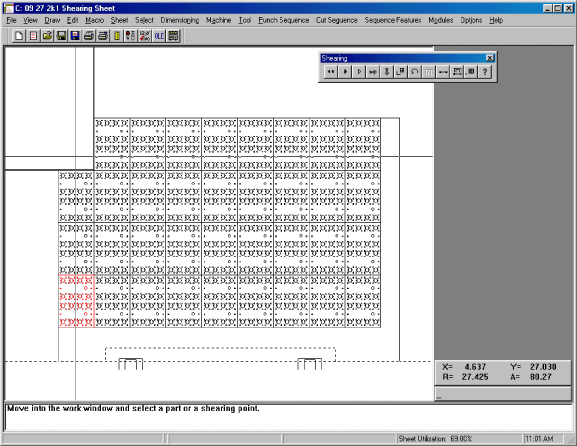
button on the Shearing toolbar. Move into the work area and position
the crosshair over the top row of parts. Click the right mouse button
to snap to the top edge. Click the left mouse button to shear the
sheet along the top.
Note: If the sheet is large enough to require repositioning,
you cannot trim horizontally. You will have to manually shear the
tops of the parts instead.
Choose Trim Horizontal and move into the
work area. If necessary, click the right mouse button to snap to the
top edge of the row of parts. Click the left mouse button to trim.
Trim Vertical

To trim the sheet vertically, select Trim
Vertical from the Shearing submenu, or click the Trim Vertical button
on the Shearing toolbar. Move into the work area and position the
crosshair over the left column of parts. Click the right mouse button
to snap to the left edge. Click the left mouse button to shear the
sheet along the left.
Choose Trim Vertical and move into the work
area. If necessary, click the right mouse button to snap to the left
edge of the column of parts. Click the left mouse button to trim.
Shearing Individual
Parts

The Manual option on the Shearing submenu
allows you to manually shear individual parts or portions of scrap
from the sheet.
To shear individual
parts out of the sheet, select Manual
from the Shearing
menu, or click the Manually Shear Sheet
button in the Shearing toolbar. You can now shear manually using one
of three methods:
To
shear along the top of a part, click the right mouse button to
snap to the top right corner, and then click the left mouse button.
To
shear along the left of a part, click the right mouse button to
snap to a line on the left side of the part, and then click the
left mouse button.
To
shear the part, move the crosshair over the part and click the
left mouse button. (As an alternative, you can use the right mouse
button to snap onto the bottom right corner of the part and then
click the left mouse button to shear.)
Select Manual from the Shearing submenu,
and click the part you want to shear manually. 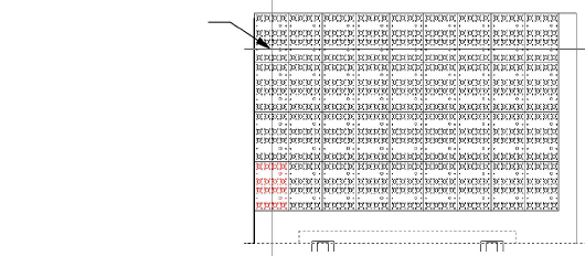
The system shears the part from the sheet.
The part disappears from the work area.
Undo

|
To reverse
the last shearing sequence, select Undo
from the Shearing
submenu, or click the Undo Shearing
button in the Shearing toolbar. The option allows you to eliminate
the last function added to the shearing sequence without resetting
the entire sequence. Note: Be careful using the Undo command.
While the option is capable of reversing multiple shearing
operations, it can also remove the original punch or cut sequencing
you assigned to the inside patterns. |
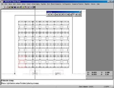
Move Clamps |

|
The Move Clamps option is available
only if the machine driver supports moving the clamps during
sequencing or shearing.
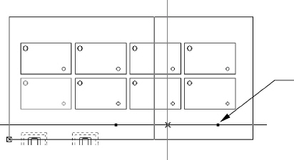
To move the clamps:
Select
Move Clamps from
the Shearing
submenu, or click the Move
Clamps button on the Shearing toolbar. Move the crosshair into the
work area. Two round markers that represent the reposition
posts begin to follow the crosshair.
Move the crosshair onto a clamp
and click the left mouse button. The system prompts you
to select the clamp. Click the left mouse button again.
The system prompts you to relocate the clamp. Move the
mouse along the X-axis of the sheet edge to position the
clamp. Repeat this step for each clamp. See the illustration
below. When you have relocated each
clamp, click the right mouse button to continue with other
sequencing activities.
|
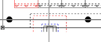
Reposition

|
Repositioning
allows you to use sheet sizes longer than your machine's maximum
X travel. The Reposition option opens the clamps and moves
them so you complete the remainder of the sheet. You can also
reposition in the reverse direction to return the clamps to
their original position so the sheet does not hang off the
edge of the table.
To reposition the clamps during a shearing sequence, select
Reposition from
the Shearing
submenu, or click the Reposition
button on the Shearing toolbar. The prompt instructs you to
move into the work area and set the reposition location. As
you move the pointer across the sheet, the reposition line
appears and the prompt asks you to choose its location. The
location of the reposition line relative to the lower left
corner of the sheet indicates the direction and distance you
want the clamps to move. As you move closer to the edge of
the sheet, you will see a rectangle following the pointer.
This represents the machine bed.
The patterns
that appear inside this rectangle are within range. When the
patterns you want to sequence with shearing functions appear
inside the rectangle, click the left mouse button. The repositioning
line locks onto the sheet, and two solid blocks that represent
the positioning posts appear. The repositioning posts follow
the pointer around the work area and a prompt instructs you
to choose their placement. Make sure the posts do not fall
inside a cutout on the part. When you are satisfied with the
location, click the left mouse button. You can continue to
sequence the sheet. To reposition back to the original location,
place the left position line at X=0.000; the clamps return
to their original location.
Notes:
For the minimum reposition,
place the right position line as close to the farthest
pattern as possible. The pattern is within range while
inside the reposition lines. When repositioning multiple
parts, you should place out-of-range parts in a separate
grid. |
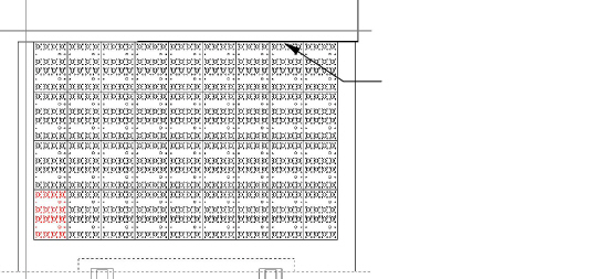
|
You must reposition if your sheet
extends beyond the table limits. While
the Add option is active, select
Reposition from the Sequence Options
window. |
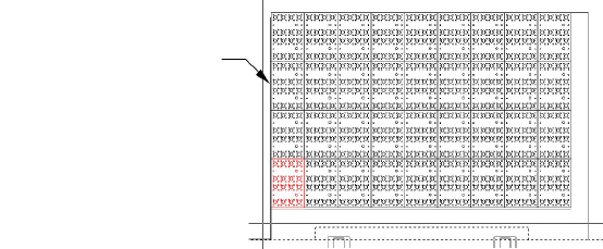
|
Use the mouse and crosshair to locate
the reposition line, and then click the left mouse button. |
|
Use the mouse and crosshair to position
the holddowns. Make sure not to locate the posts over a large
hole on the sheet, and then
click the left mouse button. |
Auto Repo or Move
Clamps

|
The Auto
Repo or Move Clamps option controls whether the system automatically
repositions or prompts you for a reposition. If you want the
system to perform an automatic reposition, select Auto Repo or Move Clamps on the Shearing
menu until a check mark appears
next to the option. If you want the auto shearing process
to stop and prompt you for a reposition when the sheet requires
a clamp movement or reposition, remove the check mark from
the option. Note: The Activate Repo button on the Shearing
toolbar is a toggle. |
Initialize or
Reset |

|
This option
prepares the sheet for shearing and resets any existing shearing
sequence. It does not affect any cutting or punching sequencing
you defined before the shearing. However, any punch or cut
sequencing you perform after shearing is reset when you select
the option. You must use Initialize or Reset before choosing
either Auto or Manual from the Shearing menu. Select
Initialize or Reset from the Shearing
submenu, or click the Initialize
or Reset Shearing button in the Shearing toolbar. The system
prompts you to confirm. Press <Y> to reset the shearing
sequence. Press <N> to cancel. |
View Shearing

|
To
see the shearing sequence, select View
from the Shearing
submenu, or click the View Shearing
button on the Shearing toolbar. Note: Use the Viewing Speed command on the
Options menu to control the redraw rate of the sequence. |
Saving the Shearing
Sheet |

|
You should
save your sheet frequently to prevent data loss during power
outages or computer crashes. If you press the <F10>
key while in Sheet view, the system saves your sheet under
its assigned name in its default folder. Note:
If you have not yet named the sheet, pressing <F10>
saves the sheet with the default name of NEW SHEET.
To save the sheet:
Make sure you are in Sheet
view. To save the sheet under a new name, select Save
As from the File menu, or click the Save As button in
the Standard toolbar. The Save As dialog box appears. If
necessary, select Sheets
(*.sht) from the
Save as type:
list. Type a name in the File name: text box. You need
not add the filename extension; the system automatically
adds the *.sht
extension. Click
the Save button to save the sheet. Click
the Close button to exit the Save As dialog
box. |