Gripper Unloading Manual
What is Gripper Unloading?
|
The Gripper Unloading
module is an optional software package that enhances the functionality
of the CADCAM System. The features in Gripper Unloader were designed
to support machines like the Behrens CB2011
.
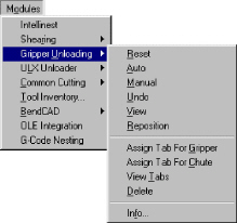
The Gripper Unloading option is found on the Modules menu. To access
the options on the Gripper Unloading submenu, you must first open
the Modules menu, and then select the option (using the mouse
or keyboard) to list the commands.
To ensure the options on the Gripper Unloading submenu are active
when you begin your session, the following conditions must be
in effect:
Your
machine driver must support gripper-unloading functions. |
|
Sheet
view must be active. You cannot use the gripper unloading
options if Part view is active. If the Info
option is active, but the remaining
options are disabled, you must use the Info
option first to specify the gripper
information. |
Quick Start Guide
The
Quick Start Guide summarizes the gripper unloading process. Review this
outline of the Gripper Unloading features. For commands or tasks you do
not fully understand, reference the appropriate section.
Start Gripper Unloading
To prepare for Gripper Unloading, launch the
CAD/CAM System. Select Sheet
from the View
menu. Sheet view must be active before you
can use any of the options on the Gripper Unloading submenu.
Load the Machine File

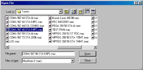
Select Open
from the File
menu, or click the Open File button in the
Standard toolbar. When the Open File dialog box appears, select
Machines (*.mac) from
the Files of type:
drop-down list. The system lists the machine files stored in the \Turrets
directory by default. If necessary, use the Look
in: drop-down list to navigate the
hierarchical folder structure. Scroll through the file list window and
click the name of the machine file. Click Open
to load the machine file. If necessary, edit
or load a material file. Click Close
to exit the Open File dialog box.
Load the Machine Driver
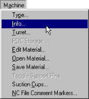
Select Info
from the Machine
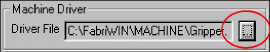
menu to open the Machine Setup window. Click
the Driver File button.
The Open dialog box displays the machine drivers stored in the \Machine
directory by default. If necessary, use the Look
in: drop-
down
list to navigate the hierarchical folder structure. Scroll through the
file list window and click the name of the driver file. If necessary,
edit or load a material file. Close the Machine Setup window.
Specify the Gripper Information
Open the Modules
menu. Select Info
from the Gripper
Unloading
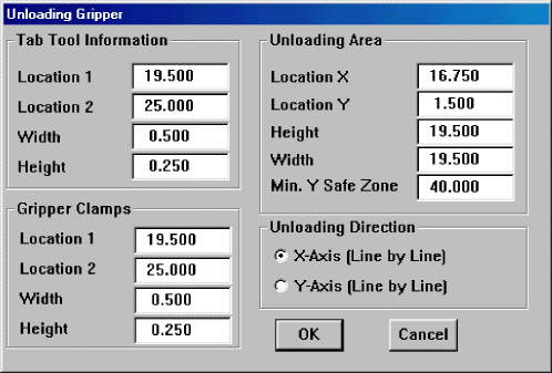
submenu to open the Unloading Gripper dialog
box. Specify the Tab Tool Information, Gripper Clamps, Unloading Area
and Unloading Direction by either typing the values in the text boxes
or by selecting the appropriate option buttons. Click OK
to save the gripper unloading information.
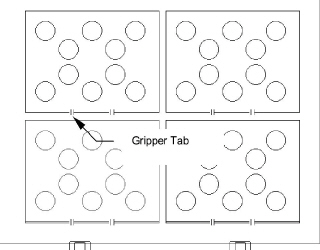
Create the Gripper Sheet

Load the parts onto the sheet and grid them
if necessary. Use the Assign Tab for
Gripper or the Assign
Tab for Chute options on the Gripper
Unloading submenu to place unloading tabs on the parts. You can also use
the respective buttons on the Gripper toolbar to place tabs on the parts.
Sequence the Gripper Functions
|
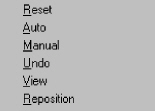
Use the
Reset,
Auto,
Manual,
Undo,
View and
Reposition options
on the Gripper Unloading
submenu to remove the parts from the
sheet.
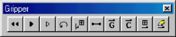
You can also use the respective buttons on the toolbar to define
the gripper sequence.

|
Save
the Gripper Sheet |

|
Select
Save As from
the File menu,
or click the Save As button in the Standard toolbar to open the
Save As dialog box. Select Sheets
(*.sht) from the Save as type:
drop-down list. Type an appropriate name in the File
name: text box. Click the
Save button
to save the gripper sheet. Click the Close
button to exit the dialog box. |
Preparation
You
must complete several steps before you can create a sheet having gripper-unloading
functions:
If necessary, activate Sheet view.
Define the sheet size and thickness.
Load the parts on the sheet.
Select and arrange the parts on the sheet.
Please reference Chapter
5: Sheet Layout in the CAD/CAM System
manual for more details. Once you have completed the part layout, you
can define the gripper-unloading functions for the sheet. The remainder
of the process involves loading a machine file and gripper driver, and
specifying the gripper information, assigning tabs for the gripper or
chute, and sequencing the sheet.
Load the Machine File

A
machine file contains the physical parameters of a machine. You must load
the correct machine file before you can define a sheet having gripper
functions. Machine files have the filename extension of *.mac, and are
stored in the \Turrets directory by default.
To load the machine file:
Select Open
from the File
menu, or click the Open File button in
the Standard toolbar. The Open File dialog box appears.
Click the Files
of type: arrow and select
Machines (*.mac) from
the drop-down list.
If necessary, use the Look
in: list to navigate the hierarchical
folder structure.
Scroll
through the file list window and click the name of the machine file
you want to load.

- Click Open to
load the machine file, and then click Close
to exit the dialog box.
Load the Machine Driver
|
The next step involves checking the machine
driver, and if necessary, selecting the correct driver that supports
gripper-unloading functions. Your machine driver must support
gripper functions before you can use them. Please contact your
CAD/CAM System representative for more information on custom drivers.
Select Info
from the Machine
menu to open the Machine Setup
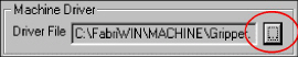
window. The Setup Values page displays by default. Click
the Driver File  button in the Machine
Driver button in the Machine
Driver
section.
When the Open dialog box appears, the name of the current
driver displays in the File
name:
text box.
If the driver is correct, then click
the Close button to exit the Open dialog box.
To load an alternate driver,
navigate through the file list and click the name of the driver
you want to load. Click the Open
button to load the driver. You
may be prompted to create or load a material file.
See the
Material Files section in Chapter 7: Machine Files of the CAD/CAM
System manual for more information. Click Save
in the Machine Setup window. |
Unloading Gripper Window
You
must specify the gripper information before you can use any of the gripper
functions. If this information already exists in the machine file, then
you only need to examine the values to ensure they are correct. If necessary,
you can view and edit the values using the Unloading Gripper window.
To
display the Unloading Gripper window:
Make sure Sheet view is active. If necessary,
select Sheet from
the View menu.
Open the Modules
menu, and highlight (select) Gripper Unloading to
open its
submenu.
Select Info
from the Gripper
Unloading submenu. When the Unloading
Gripper window opens, the contents of the Location
1 text box in the Tab Tool Information
section are selected by default.
Type
the values in the various text boxes. You can navigate the text box
fields within the window using a combination of the <Tab> and
<Shift> keys. Press <Tab> to move to the next field, or
<Shift> + <Tab> to select the contents of the previous
field.
When the information appears correct, click
the OK button
to save the changes and to exit the Unloading Gripper window.
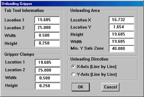
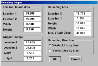
Tab Tool Information
|
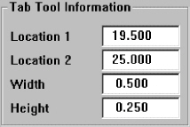
The Tab Tool Information
options allow you to specify the values for the tab locations
on the part as measured from the bottom left corner of the part. |
Tab Tool Information
Options |
Location 1 This
is the first tab measured from the bottom
left corner of the part.
Location 2 This is the second tab measured
from the bottom
left corner of the part.
Width The X dimension of the microjoint
depicting the
tab on the part.
Height The size of the slitting tool between
parts. |
Gripper Clamps |
Note: You will use the Assign Tab for Gripper
or Assign Tab for Chute options to assign tabs. |
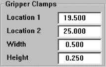
|
The Gripper Clamp
values specify the locations of the first and second clamps, as
measured from the bottom left corner of the part. You may need
to change this information according to the sheet layout and part
sizes. |
Gripper Clamps Information
Options |
Location 1 The first
Y dimension measured from the bottom left
of the part.
Location 2 The second Y dimension measured
from the
bottom left of the part.
Width The X dimension for the gripper clamps.
Height The Y dimension for the gripper clamps. |
Unloading
Area
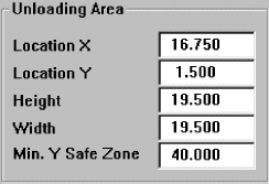 |
The Location X and
Location Y values
for the unloading area are derived from the machine's zero
(center of the tool). The information for the Unloading Area (Location
X, Location Y, Height,
Width and Min. Y Safe Zone) is found in your machine's manual. |
Unloading Direction
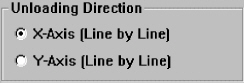
The Unloading Direction section allows
you to specify the direction for the gripper.
Unloading Direction Options
X-Axis
(Line by Line) This instructs the CAD/CAM System to move in the X-axis
before moving in the Y- axis.
Y-Axis
(Line by Line) This instructs the CAD/CAM System to move in the Y-axis
before moving in the X- axis.
Creating a Sheet with Gripper Functions
Once you have loaded the correct machine file
and gripper driver, and specified the correct values in the Unloading
Gripper window, you can add the actual gripper functions to the sheet.
This involves placing either gripper or chute tabs on the sheet.
See Assign Tabs for the Gripper and Assign
Tabs for the Chute.
Note: Make
sure to check the gripper information before you begin. Use the
Info option
on the Gripper Unloading submenu
to open the Unloading Gripper window.
Assign Tabs for the Gripper
 For
parts large enough for the gripper, use the Assign
Tab for Gripper option on the
Gripper Unloading submenu,
or click the Assign Tool Tab for Gripper button in the Gripper toolbar.
For
parts large enough for the gripper, use the Assign
Tab for Gripper option on the
Gripper Unloading submenu,
or click the Assign Tool Tab for Gripper button in the Gripper toolbar.
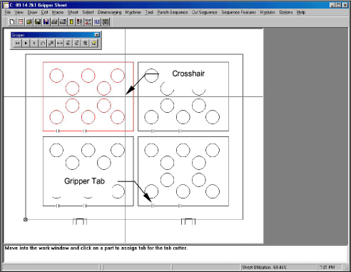
The
system prompts you to “Move into the work window and click on a part to
assign tabs for the tab cutter.” Move the crosshair over each part or
grid of parts you want to unload using the gripper. The gripper tabs appear
when you click an individual part or a grid of parts.
Notes:
If
the message, “The part is too small to assign tool tab for gripper
unloading” displays, try the Assign Tabs for the Chute option instead.
The Tab Tool Information values in the Unloading Gripper window determine
the size of parts that can be unloaded using the gripper.
If
you click a grid, all parts belonging to that grid are assigned gripper
tabs.
Assign Tabs for the Chute

If the parts or grids of parts are too small
for the gripper, you can try using the Assign
Tab for Chute option on the
Gripper Unloading submenu.
You can also click the Assign Tool Tab for Chute button on the Gripper
toolbar to activate the command.
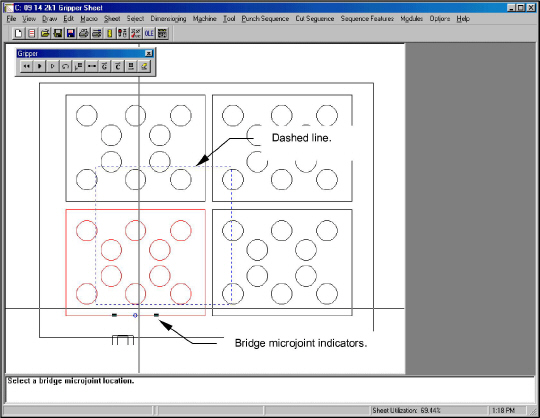
The
system prompts you to “Select an arc or a line to place a bridge microjoint.”
Move the crosshair over a part or grid of parts you want to drop down
the chute. Move the crosshair over a part or a grid of parts and click
the left mouse button. A dashed outline that represents the chute and
two bridge microjoint indicators snap to the nearest line or arc.
The system now prompts you to “Select a bridge microjoint location.” Move
the mouse from left to right until the microjoint indicators are in the
correct position. Click the left mouse button to place the tabs.
Correcting the Sheet Setup
If
while placing gripper or chute tabs produces unwanted results, you can
choose to display the microjoints, and if necessary, remove them from
the sheet.
View
Tabs

|
To determine
which parts have gripper tabs or chute tabs, select View Tabs from
the Gripper Unloading
submenu, or click the View Tool Tabs
button on the Gripper toolbar. |
Delete |

|
To remove a
tab for the gripper or chute, select Delete
from the Gripper
Unloading submenu, or click
the Delete Tool Tab button on the Gripper toolbar. Move into the
work area and click the part or grid of parts. The tabs are deleted
from the sheet. |
Note: If
you click a grid using the Delete option, all the tabs are removed from
that grid on the sheet.
Sequence the Sheet
Sequence
the sheet as you normally would using the options on the Punch Sequence
menu, the Sequence Features menu, and the items listed in the Sequence
Options window.
When you arrive at the point where you want
to sequence with gripper features, see
Sequencing Gripper Features.
Sequencing Gripper Features
The
gripper options remove the parts from the sheet. The Auto, Manual, View
and Reposition options sequence the gripper features. The Undo and Reset
options allow you to correct errors in the gripper sequencing.
Auto

|
Use the
Auto option
on the Gripper Unloading
submenu, or click the Auto Unload
button on the Gripper toolbar, to automatically sequence the unloading
of parts. The CAD/CAM System uses the gripper to remove the parts
using the gripper tabs. For parts that have chute tabs, the system
automatically drops them down the chute. If the parts marked for
the chute do not fit within the chute's boundary, the system asks
if the part should drop down the chute. Press <Y> for “Yes”
or <N> for “No.” If the parts are out of range, you must
reposition the sheet before you can use the Auto command.
See Reposition. |
Manual |

|
Use the
Manual option
on the Gripper Unloading
submenu, or click the Manually Unload
Part button on the Gripper toolbar when you want to decide which
parts to unload using the gripper or to drop down the chute. Select
Manual from
the Gripper Unloading submenu,
and then move into the work area. Click each part you want to
remove. If you click a part that does not fit within the chute's
boundary, the system prompts you to confirm. Press <Y> for
“Yes” or <N> for “No.” |
Undo

|
Use the
Undo command
on the Gripper Unloading
submenu, or click the Undo Unloading
button on the Gripper toolbar, to reverse the last gripper command
you selected. You can then continue with your sequencing. |
Reset |

|
The Reset option
on the Gripper Unloading
submenu allows you to clear any previous
gripper sequences. To clear the gripper sequence, select
Reset from
the Gripper Unloading submenu,
or click the Reset Unloading button in the Gripper toolbar. The
system prompts you to confirm the action. Press <Y> to reset
the sequence or <N> to cancel. |
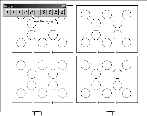
View |

|
To see the gripper
sequence, select View
from the Gripper
Unloading
submenu, or click the View Unloading
button in the Gripper toolbar.
Note:
To specify the viewing speed, use the Viewing Speed command on
the Options menu. |
Reposition |

|
Repositioning
allows you to use sheet sizes longer than your machine's maximum
X travel. The repositioning function opens the clamps and moves
them so you can complete the remainder of the sheet. You can also
reposition in the reverse direction to return the clamps so the
sheet does not hang off the edge of the table. To reposition the
clamps during a gripper sequence, select Reposition
from the Gripper
Unloading submenu,
or click the Reposition for Unloading button on the Gripper toolbar.
The prompt instructs you to move into the work area and set the
reposition location. As you move the pointer across the sheet,
the reposition line appears and prompt asks you to choose its
location. The location of the reposition line relative to the
lower left corner of the sheet indicates the direction and distance
you want the clamps to move.
As you move closer to the left edge of the sheet, you will see
a rectangle following the pointer. This represents the machine
bed. The patterns that appear inside this rectangle are within
range. When the patterns you want to sequence with gripper functions
appear inside the rectangle, click the left mouse button. The
repositioning line locks onto the sheet, and two solid blocks
that represent the repositioning posts appear. The
repositioning posts follow the pointer around the work area and
a prompt instructs you to choose their placement. Make sure the
posts do not fall inside a cutout on the part. When you are satisfied
with the location, click the left mouse button. Use the other
options to complete the gripper sequencing after repositioning.
|
Saving the Gripper Sheet

You
should save your sheet frequently to prevent data loss during power outages
or computer crashes. If you press the <F10> key while in Sheet view,
the system saves your sheet under its assigned name in its default folder.
Note: If
you have not yet named the sheet, pressing <F10> saves the sheet
with the default name of NEW SHEET.
To
save the sheet:
Make
sure you are in Sheet view. To save the sheet under a new name, select
Save As from the File menu, or click the Save As button in the Standard
toolbar. The Save As dialog box appears.
If necessary, select Sheets
(*.sht) from the Save
as type: list. Type a name in the
File name: text box. You need not add the filename extension; the
system automatically adds the *.sht
extension.
Click the Save
button to save the sheet. Click the
Close button
to exit the Save As dialog box.