This section explains BendCAM integration as it relates to the CAD/CAM System. Please refer to your BendCAM documentation for more information.
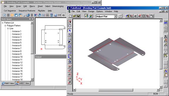
BendCAM integration converts 2D part drawings into 3D models. You can draw each flange view without regard for any layout calculations. You then transfer the flange geometry to BendCAM, creating a 3D model. You can manipulate flange locations, bend radii, bend types, bend deductions, add bend relief and examine the 3D model for any potential problems. If you make any design changes, you can reverse the process and transfer the 3D model information to the CAD/CAM System, which will create an updated flat pattern layout. This design environment helps to eliminate common design errors and programming mistakes.
Note: The CAD/CAM System and BendCAM must be running simultaneously before you can exchange data. You can resize each program window to view both interfaces during the session.
|
|
The Process option on the BendCAM submenu initializes the interface between the system and BendCAM. Any flange information previously chosen is reset and new BendCAM part is started. |
|
|
View highlights flanges in the CAD/CAM System that have already been sent to BendCAM. |
|
|
When Send and Connect a Flange is selected, you are prompted to choose the flange edges for BendCAM. Move the cursor into the work area until it touches the edge of one of the flanges that you want to connect to another flange, and then click the left mouse button. Next, move the cursor to the adjoining edge of the connecting flange and click the left mouse button. Once the two adjoining edges are highlighted, click the right mouse button. |
|
The options in the Bend Parameters window allow you to manipulate the position of the current flange. When the information is correct, click OK. If OK is selected, the system will keep the current parameters as the default parameters when the user assigns bends next time. The bend geometry is sent and a 3D part appears in BendCAM. |
|
|
|
|
|
Option |
Description |
|
Bend Type |
The Front and Back options in this section allow you to determine the direction of the bend. |
|
Front |
Select Front if the bend direction is forward. |
|
Back |
Select Back if the bend direction is backward. |
|
Drop-down list |
From the drop-down list select V-Air or V-Coining.
Note: V-Air (Air Bending) is done with the punch touching the workpiece, but not bottoming in the lower cavity of the die. V-Coining (also called Bottoming) is the bending process where the punch and the workpiece bottom on the die. |
|
V Width |
Select a V Width from the drop-down and the program will automatically calculate a Bend factor, which is given below in the Bend Deduction field. |
|
Angle |
This option allows you to specify the bend angle. The angle should be subtracted from 180 Deg. Example: a 45 Deg. bend should be entered as 135.00. Refer to your BendCAM documentation for more information. |
|
Inside Radius |
This option allows you to specify the inside bend radius. |
|
Group ID |
The Group ID option allows you to define a series of flanges as belonging to a particular group. You can then apply global changes to the grouped set of flanges in BendCAM. |
|
Bend Deduction |
The Bend Deduction is auto-calculated when a bend type and V Width are selected. Any value for the bend deduction may be entered in this text box. |
|
Use BendCAM Defaults |
Selecting this option allows you to use the bend information already specified in BendCAM. |
|
|
These two options allow you to edit flange geometry in the system and send the new geometry to BendCAM without changing the previously transmitted bend information. |
|
|
|
|
|
Send Flat Layout allows you to transfer a developed flat pattern to BendCAM to create a 3D model. |
|
|
This option allows you to send the geometry of a single flange sent to BendCAM. You should select this option only if the flange that you want to send occupies the work area. All geometry in the work area is sent to BendCAM. |
|
|
Clear Flange Connection allows you to clear the geometry of a single flange sent to BendCAM. |
|
|
Clear All Flange Connections allows you to clear all the flange geometries that you sent to BendCAM. |
The following options allow you to modify or remove flange connections that you have already transferred to BendCAM.
|
|
Edit Bends allows you change any of the parameters in the Bend Parameters window. |
|
|
Detect and Show Bend Lines allows you to highlight bend lines on a previously developed flat pattern layout to ensure they are properly detected prior to using the Send Flat Layout option. |
|
|
This option allows you to delete all bend lines that are detected on a previously developed flat pattern layout. |